E6. Wearable AR: Spatial Awareness
Learning Outcomes
- Differentiate wearable AR from mobile AR and describe its advantages for engineering and spatial workflows. Understand how continuous spatial mapping, anchoring, and occlusion make wearable AR ideal for real-world problem-solving and visualization across design, simulation, and field applications.
- Develop and deploy passthrough mixed reality experiences on modern wearable AR devices. Learn how to configure OpenXR with camera passthrough on devices such as the Meta Quest 3 and Magic Leap 2, integrate AR Foundation’s AR Camera Manager and AR Background Renderer, and test interactions using hands or controllers in mixed reality.
- Set up Unity projects for both Meta Quest 3 and Magic Leap 2 development. Gain experience with platform-specific tools — including the Meta XR SDK and Magic Leap Hub — install AR Foundation and each device’s XR plugin, and build/deploy directly to the headset for live testing.
- Implement plane detection and surface anchoring in wearable AR. Explore how ARPlaneManager identifies horizontal and vertical surfaces across devices, and practice attaching virtual content to detected planes for stable and spatially consistent placement.
- Explain and apply environment meshing for spatial awareness and occlusion. Study how ARMeshManager reconstructs the environment in real time, how assigning an AR → Occlusion material enables invisible occlusion, and how these meshes improve physical realism and collision detection.
- Configure and test spatial audio in wearable AR applications. Set up spatial audio systems using Unity’s built-in spatializers or platform-specific components such as MLListener and MLPointSource, and evaluate how head tracking, directionality, and distance cues enhance mixed-reality immersion.
What Is Wearable AR?
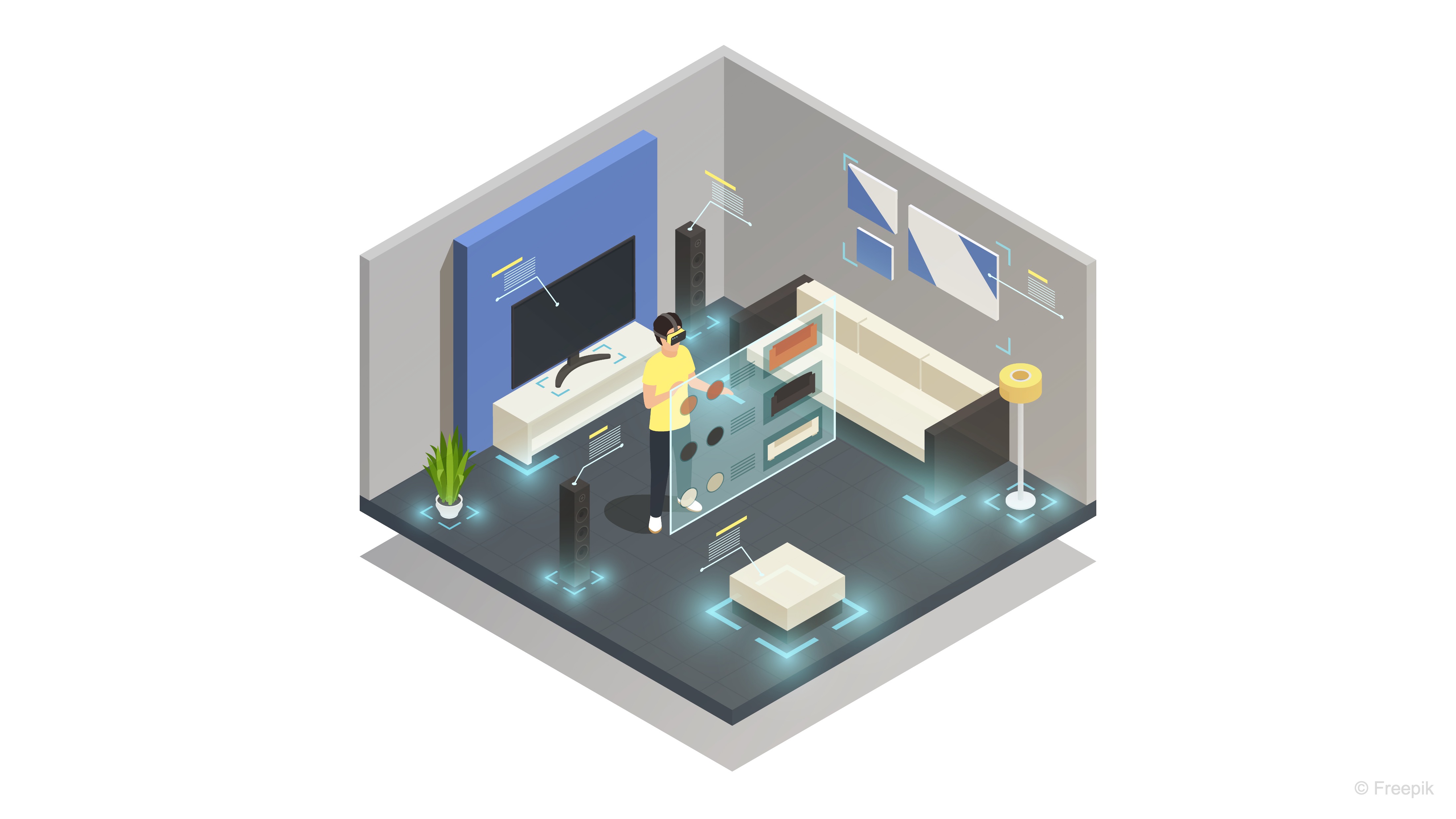
Wearable AR — also referred to as head-mounted AR, headworn AR, or spatial AR — seamlessly blends digital content with the physical world through continuous, real-time spatial understanding. Devices like the Meta Quest 3, Magic Leap 2, and HoloLens 2 exemplify this technology. These systems use an array of cameras, depth sensors, and advanced perception algorithms to scan, reconstruct, and interpret the user’s environment. This live spatial mapping allows virtual objects to anchor, occlude, and interact naturally with real-world geometry, aligning digital content with the user’s physical space. The strength of wearable AR lies in its ability to bind digital experiences directly to reality, creating a unified, immersive interface that feels physically present and responsive. This capability is transformative across domains — from immersive entertainment and design visualization to industrial training, medical applications, and field engineering — where digital information must coexist meaningfully with the real world.
Use Cases
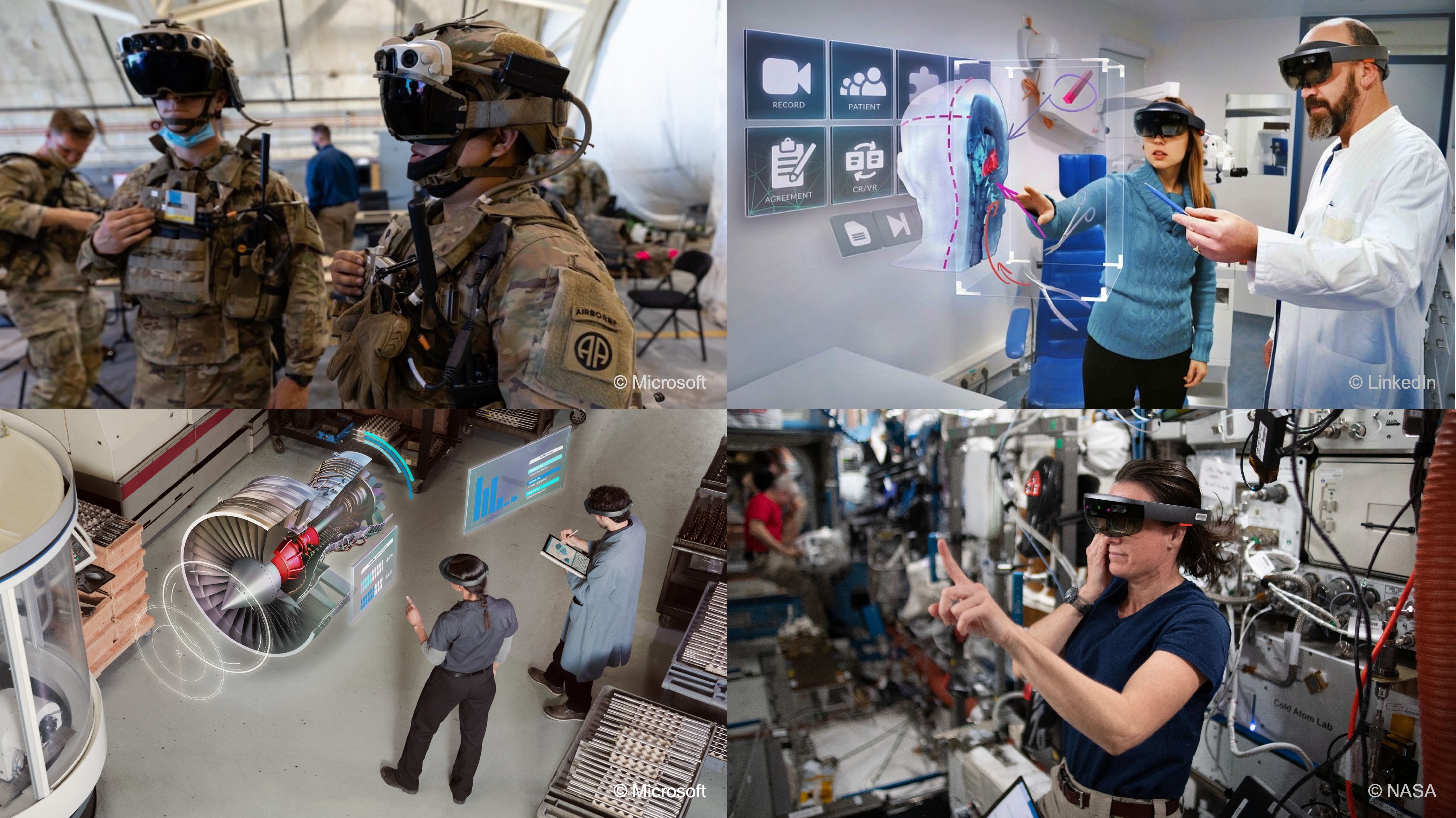
Wearable AR offers a comprehensive suite of capabilities that allow users to interact with the world in new and innovative ways to enhance productivity, decision-making, and safety in engineering, manufacturing, and beyond. Common use cases include:
-
Visualization of Complex Assemblies: Engineers can overlay 3D CAD models directly onto physical machinery or structures to see how parts fit together, identifying potential issues or improvements before actual construction or assembly begins.
-
Guided Assembly and Maintenance: Wearable AR devices can provide real-time, holographic instructions that are anchored to specific parts of the machinery. This step-by-step guidance helps technicians assemble or maintain equipment with high precision, reducing human error and downtime.
-
Fit and Tolerance Validation: Wearable AR can detect real-world surfaces and edges, then mesh virtual parts against these physical components. This helps engineers check for fit and tolerance issues in real-time, improving product design and quality assurance processes.
-
Operator Training: AR can simulate realistic operational environments for training purposes, providing operators with spatialized sound cues and natural input methods to practice tasks without the need for actual physical equipment. This is particularly valuable for hazardous or complex procedures that require practice before they can be performed in the real world.
-
Remote Collaboration: Wearable AR enables teams to collaborate across distances by sharing spatial anchors and telepresence views that are tied to specific factory zones or workspaces. This allows team members to interact with virtual representations of objects and provide guidance or feedback in real-time, regardless of their physical location.
-
Prototyping and Design Iteration: Engineers can quickly test and iterate on prototypes by virtually adding or modifying parts in their real-world environments. This accelerates the design process and reduces the time and cost associated with physical prototyping.
-
Enhanced Safety and Hazard Detection: In high-risk environments, wearable AR can be used to identify hazards and provide real-time safety alerts or guidance. This could include highlighting unsafe areas, offering safety reminders, or guiding workers through safe operations.
-
Interactive Customer Demonstrations: In product development and marketing, AR can be used to demonstrate products in an interactive, immersive way. Customers or stakeholders can explore virtual models of products within their own environments, making the sales or design process more engaging and effective.
While this content primarily focuses on Meta Quest 3 and Magic Leap 2 as representatives of passthrough and see-through AR, respectively, the principles and concepts discussed apply broadly to other devices, such as HoloLens 2, HTC VIVE, and even Apple Vision Pro, enabling a wide range of AR applications across different industries.
Spatial Awareness
For wearable AR devices like Magic Leap 2 or HoloLens 2, spatial awareness is foundational to blending digital content seamlessly with the physical environment. These systems rely on spatial mapping technologies that allow virtual objects to behave as if they truly exist in the same space as the user.
-
Plane Detection: Automatically discovers horizontal and vertical planes (floors, tables, walls) so you can place and align virtual models in real space. In wearable AR, this enables stable placement of digital instructions, guides, or schematics directly on relevant surfaces in the user’s field of view.
-
Meshing: Builds a full 3D mesh of your environment—capturing every surface, corner, and obstacle—for physics interactions, collision testing, and realistic occlusion. This continuous environmental mapping allows AR headsets to adapt content dynamically as the user moves through complex spaces like factory floors or construction sites.
-
Occlusion: Uses meshed geometry (or depth data) to hide virtual objects behind real‑world objects, preserving correct depth cues and immersion. For wearable AR, this ensures that virtual overlays respect real-world positioning, which is critical for training simulations and precise assembly tasks.
-
Spatial Audio: Renders sounds in true 3D around you—bouncing off walls and attenuating behind obstacles—so that audio cues draw your attention to critical areas in a training or simulation scenario. With wearable AR, spatial audio enhances situational awareness, guiding users even when visual attention is occupied or obstructed.
These core spatial awareness topics will be covered in the remainder of this session. They provide the foundation for creating spatially aware, wearable AR apps in practical scenarios.
Tracking Objects
Wearable AR devices excel at recognizing and tracking objects in the real world, enabling persistent and context-aware interactions. This capability ensures that digital overlays remain accurately positioned even as the user or environment changes.
-
Image Tracking: Detects printed markers (QR, ArUco, barcodes) to instantly anchor content to precise physical locations—ideal for equipment tagging, part identification, and AR‑driven instructions. On headsets, this allows hands-free access to step-by-step guidance or technical data whenever a tagged object is viewed.
-
Spatial Anchors: Saves and restores world‑locked anchor points across sessions, letting users reopen an application and see holograms exactly where they left them—crucial for multi‑day inspections or collaborative walkthroughs. In wearable AR, this persistence ensures that project progress or inspection notes remain tied to specific machinery or locations without re-calibration.
Image tracking and spatial anchors will be covered in E7. These concepts are essential for creating stable and precise AR experiences.
Multimodal User Input
Wearable AR devices provide a range of input methods that let users interact with digital content in the most natural or practical way for their environment. These multimodal options enhance flexibility, whether users are hands-free, operating tools, or navigating complex data.
-
Controller Inputs: Leverages the controller’s bumper, trigger, touchpad and/or buttons to navigate menus, manipulate 3D gizmos, or scrub through timelines. In wearable AR, the controller provides precision and tactile feedback for tasks like CAD manipulation or detailed configuration in field applications.
-
Voice Commands: Offers hands‑free control and menu navigation via custom voice intents—helpful in scenarios where users’ hands are busy handling tools or equipment. For wearable AR users, this enables uninterrupted workflows, such as technicians calling up schematics while actively servicing machinery.
-
Hand Gestures: Allows intuitive pinch, grasp, and point gestures to pick up, rotate, or scale virtual objects—mimicking real‑world tool interactions without a controller. This gesture control in wearable AR fosters natural interaction in sterile or hazardous environments where physical controllers aren’t practical.
-
Gaze: Detects gaze direction, blinks, and fixation points to highlight or select UI elements just by looking at them—enabling faster, more natural workflows and powerful analytics on user attention. On head-mounted devices, gaze tracking enhances UI responsiveness and can streamline data collection on how users engage with complex visual information.
These multimodal user inputs for Magic Leap 2, including controller inputs, voice commands, hand gestures, and gaze, will be covered in E8. Mastering these concepts will enable you to create more natural and intuitive interaction with AR environments.
Plane Detection
Plane detection enables AR devices to identify large, flat surfaces in the user’s environment—such as floors, tables, walls, and ceilings—by analyzing the spatial mesh generated by onboard sensors. This capability is fundamental in AR experiences because it allows virtual objects to be accurately positioned and anchored to real-world surfaces, making them appear as if they truly exist within the physical space. Plane detection not only enhances realism by keeping virtual content “grounded” but also supports interactions like hit-testing, collision detection, and occlusion with the physical world.
The virtual V8 engine from XFactory can be placed onto the detected physical floor surface using
ARPlaneManager.trackables. Once anchored, the engine remains stable and aligned with the real-world plane, even as the user moves around. If the user points the device at a vertical plane like a wall or equipment rack, raycasting can be used to enable contextual interactions—such as triggering an exploded view of the engine or displaying specifications—only when the engine is near these surfaces, simulating proximity-aware behavior.
Core Concepts
-
AR Foundation: Unity’s cross-platform framework for developing augmented and mixed reality experiences across devices such as Meta Quest 3, Magic Leap 2, HoloLens, and mobile AR platforms like ARKit and ARCore. AR Foundation abstracts platform-specific SDKs into a unified API, allowing developers to build once and deploy across multiple XR ecosystems. In this tutorial, we’ll use AR Foundation’s
ARPlaneManagerto enable real-time plane detection on both Quest 3 and Magic Leap 2. -
ARPlaneManager: A core AR Foundation component responsible for discovering, tracking, and updating information about flat surfaces in the environment. It exposes detected planes via thetrackablescollection and provides events when planes are added, updated, or removed. This enables you to visualize surfaces, anchor virtual objects, or drive spatial interactions dynamically as the user moves through their environment. - Platform Plane Subsystems: Each supported device implements its own version of Unity’s
XRPlaneSubsystemunder AR Foundation’s abstraction layer.- On Quest 3, plane detection is handled through the Meta OpenXR Plane Subsystem, which processes headset sensor data to identify horizontal surfaces like floors and tables.
- On Magic Leap 2, the Magic Leap Planes Subsystem performs a similar function using spatial mapping and depth sensors to detect planar regions around the user. Understanding these subsystems helps explain device-specific differences in accuracy, performance, and available plane types.
- Platform-Specific Query Structures:
- Quest 3: Plane detection is generally configured through AR Foundation without custom query APIs. You can adjust detection mode (horizontal, vertical, or both) and visualization prefab to fit the application.
- Magic Leap 2: Offers an additional layer of configurability through the
PlanesQuerystructure, which defines parameters such as search volume, plane count limits, and size thresholds. Developers can fine-tune these settings to optimize for performance and precision in different scenarios.
- Advanced Plane Query Flags: On platforms like Magic Leap 2, additional flags (e.g.,
MLPlanesQueryFlags) can specify how plane data is retrieved:- Polygons: Retrieve full polygon outlines instead of simple bounding boxes.
- Semantic Types: Filter planes by meaning (e.g., floor, wall, ceiling).
- Inner Planes: Detect holes or voids within larger surfaces.
- Permissions and Device Considerations:
Some devices, such as Magic Leap 2, require explicit runtime permissions for spatial mapping. Always handle permission requests gracefully, ensuring users understand why access to spatial data is needed. Quest 3 typically handles these permissions automatically through system-level prompts when deploying an app with AR capabilities.
By configuring plane detection appropriately for each platform—such as focusing on horizontal planes with sufficient size and enabling polygon visualization—you can ensure that virtual objects are placed accurately and consistently in the user’s physical environment.
AR Planes on Meta Quest 3
Let’s set up and run Unity’s Mixed Reality Example for Meta-OpenXR project for Meta Quest 3, explore how AR Foundation handles plane detection and passthrough on Quest 3, experiment with interaction systems and spatial UI, and extend the sample project to build your own interactive passthrough AR experience.
- Project Setup:
- Clone or download the Mixed Reality Example for Meta-OpenXR project:
git clone https://github.com/Unity-Technologies/MixedReality-Meta-OpenXR-Example.gitOr download it as a ZIP and extract it locally.

- Open the project in Unity 2022.3 LTS or Unity 6 (or higher). Use GitHub Copilot if needed to resolve any compile issues if using Unity 6+.
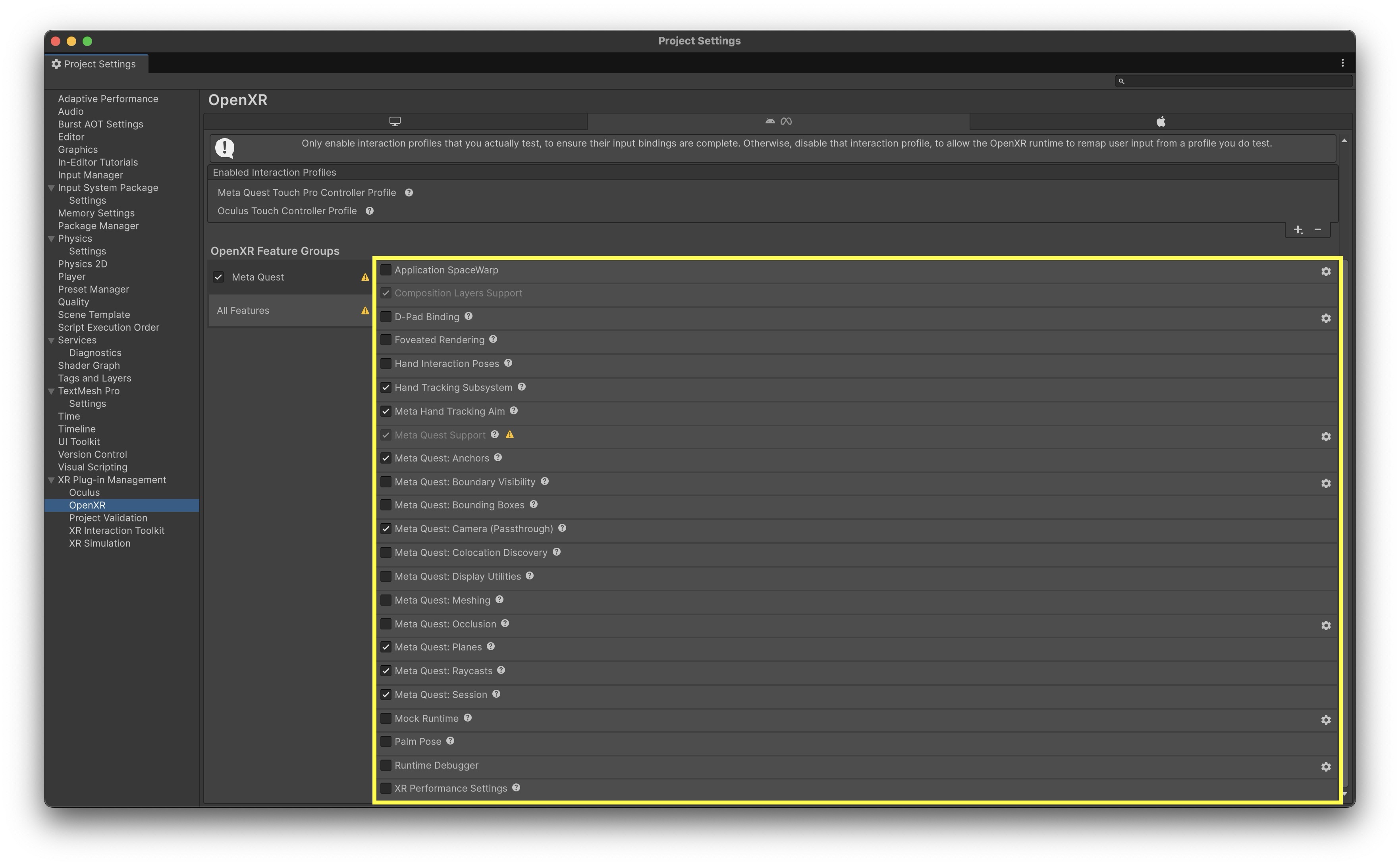
- Switch the build platform to Android and enable OpenXR with the Meta XR Feature Group for Quest support.
-
Note that plane detection and passthrough only function on a built Android app, not in the Unity Editor Play mode.
- Clone or download the Mixed Reality Example for Meta-OpenXR project:
- Scene Overview & Setup:
- Open the scene at
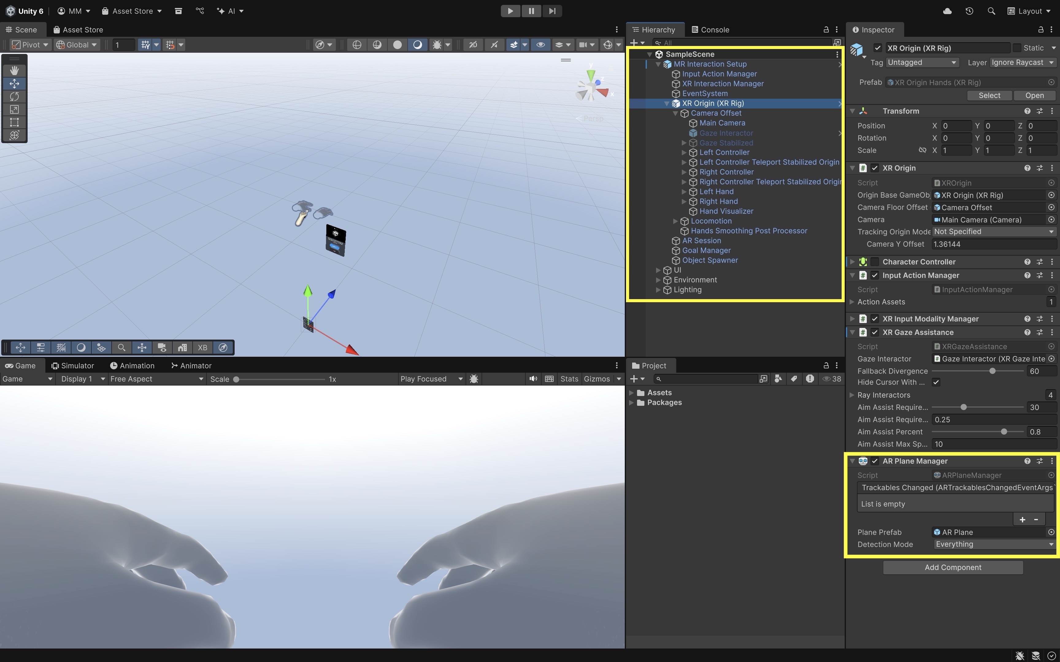
Assets/Scenes/SampleScene.unityto explore the key GameObjects. MR Interaction Setupconfigures theXR Origin, camera, input systems, and plane detection.Main Cameracontains theAR Camera Managerenabling passthrough.Object Spawnerspawns interactable prefabs using hand or controller triggers.Spatial UI Elementsare floating panels and menus for AR interaction examples.- The
XR OrigininsideMR Interaction Setupmanages player position, tracking space, and input systems. - Input systems include
ControllerandHand TrackingwithDirect,Ray, andPoke Interactorspowered by the XR Interaction Toolkit. - The
AR Session(underMR Interaction Setup) controls the AR tracking lifecycle. - The
AR Plane Manager(on theXR Origin) detects and visualizes surfaces like floors and tables. - Configure detection mode as
Horizontal(orEverythingif desired) and assign a prefab for plane visualization. -
Ensure Room Setup is complete on the Quest headset with at least one table or flat surface before running the app.
- Open the scene at
- Passthrough Configuration:
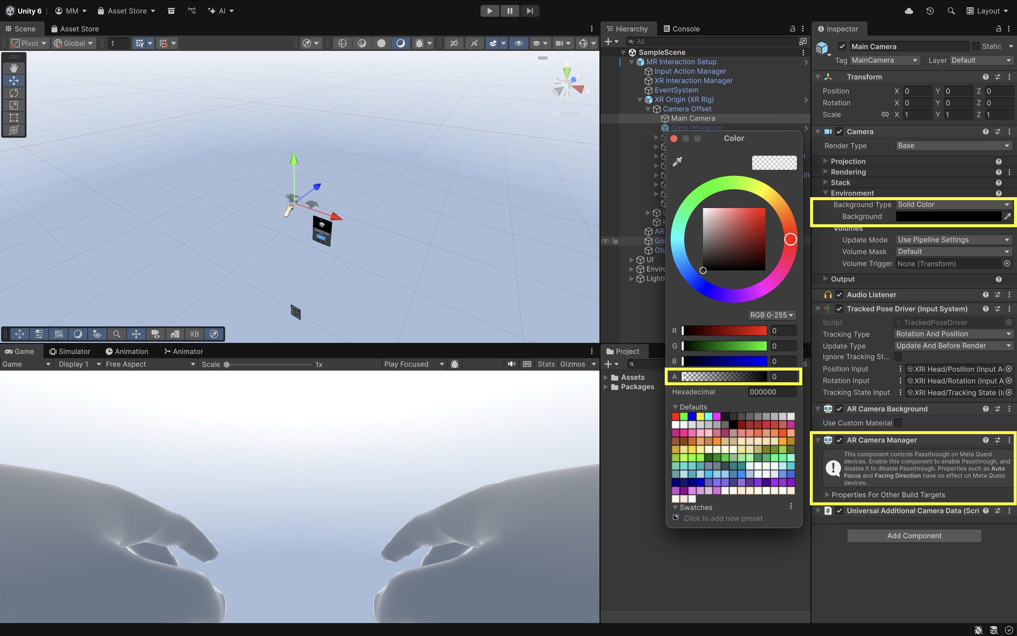
- The
AR Camera Manageron theMain Cameraenables passthrough rendering. - Set the camera background color to black with 0 alpha to make the real-world view visible.
-
This setup overlays 3D content seamlessly into the physical environment.
- The
- Object Spawner and Interactables:
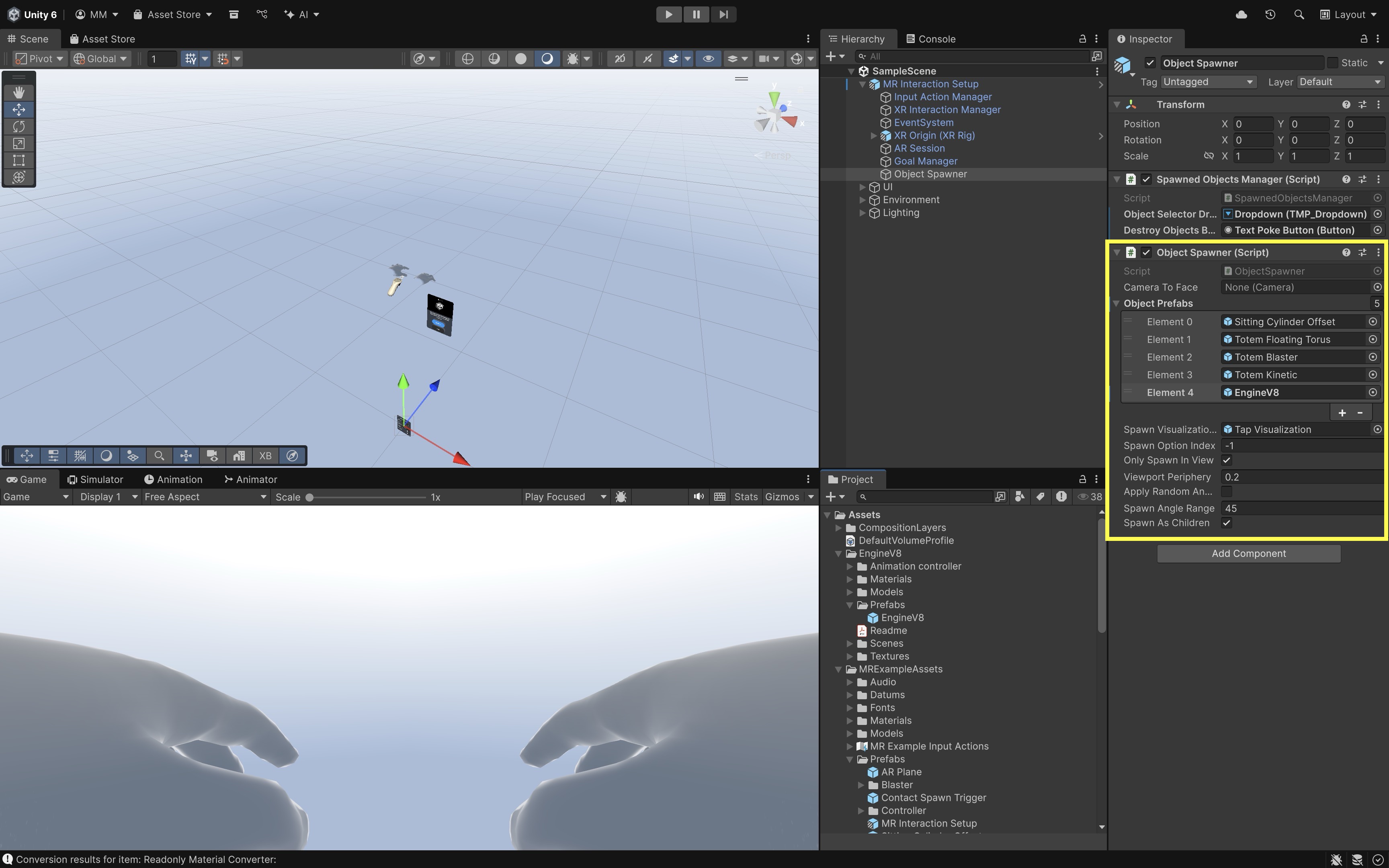
- The
Object Spawner(insideMR Interaction Setup) spawns prefabs when triggered by a hand or controller. - Interactable prefabs (e.g.,
Sitting Cylinder,Totem Floating Torus,Totem Kinetic,Totem Blaster) useXR Grab Interactable, with aColliderandRigidbodyfor physics. You can include your custom prefabs as well (e.g.,EngineV8). -
Each prefab demonstrates different interaction behaviors such as physics-based grabbing or plane-constrained movement.
- The
- Affordance System:
- Provides visual and audio feedback for user interactions.
Color Affordance Receiverchanges object color on interaction.Audio Affordance Receiverplays sounds based on user input.- Themes for affordances are located in
Assets/MRExampleAssets/Themes.
- Spatial UI and Coaching Elements:
- The
Hand Menuappears when the user’s palm faces upward, featuring toggles, buttons, and dropdowns. - The
Coaching UIis managed by theGoal Manager, which guides users through onboarding steps. -
The
Spatial Panel Manipulatorallows users to move or rotate a floating video player canvas.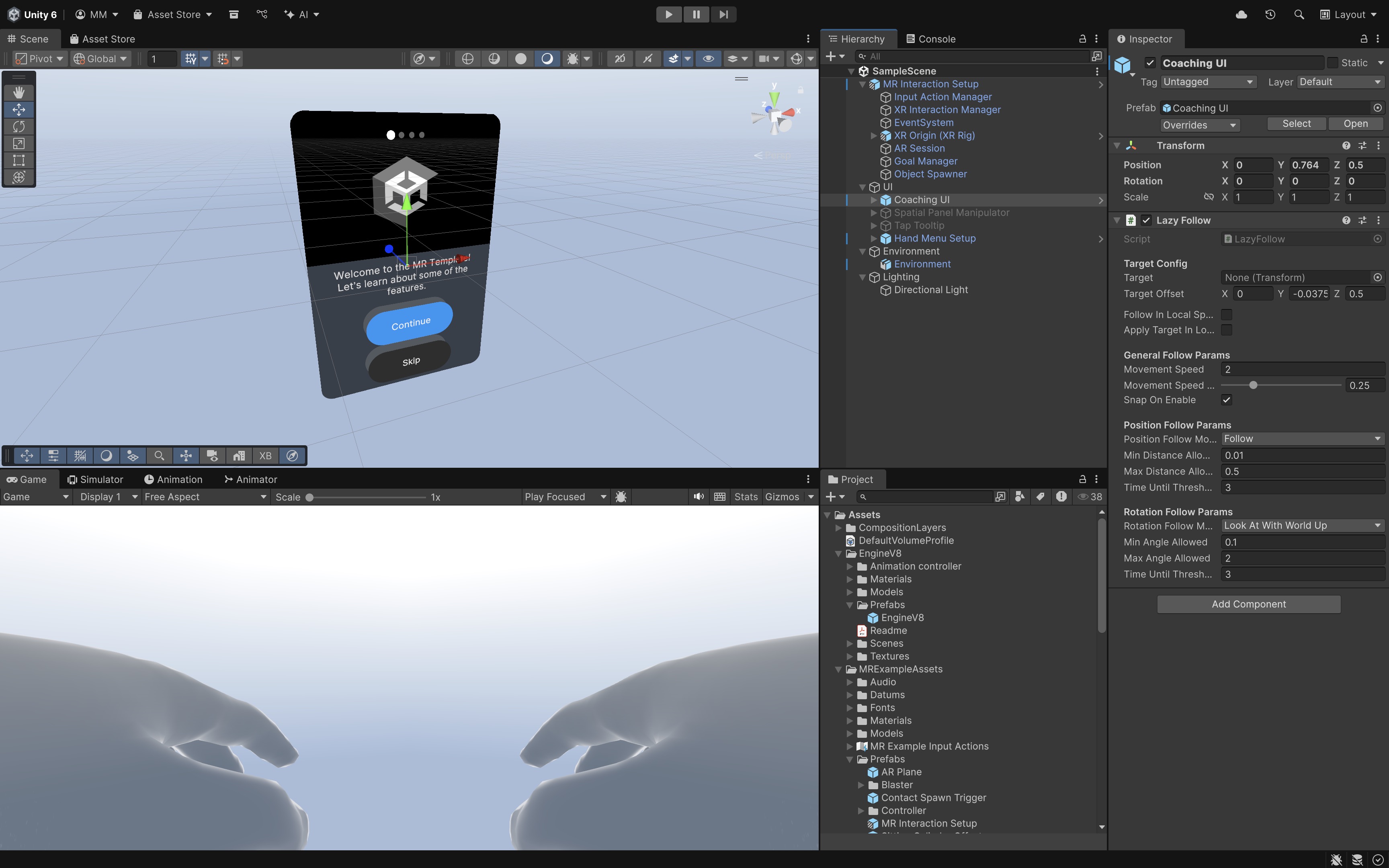
- The
- Building for Quest 3:
- Click
File > Build Profiles. - Switch the target platform to
Android. - Connect Quest 3 via USB in Developer Mode and select
Build and Run.
- Click
Exercises and Extensions: Customize plane visualization with transparent or grid shaders; add new prefabs to the Object Spawner and modify spawn behaviors; or enable vertical plane detection and observe how the scene behaves differently.
AR Planes on Magic Leap 2
To better understand the functionality and affordances of plane detection in wearable AR, let’s work on an example of implementing plane detection on Magic Leap 2 and placing the Engine V8 model from XFactory on detected floors. To make this happen, we will place the Engine V8 prefab on the first detected horizontal plane, while offsetting it from the headset forward direction so it doesn’t collide with the user. We will also allow the user to rotate the engine around the Y-axis using the Magic Leap 2 controller touchpad (left/right swipe).
- Setup the Scene:
- Open the Magic Leap examples project opened in Unity.
- Open the
Planes.unityscene, save it asPlaneDetection.unity. To avoid mixing things up with Magic Leap’s preconfigured scenes, save it in a separate folder (e.g.,Assets > Scenes > XRE Tutorials). - Optionally, disable the
UserInterfaceGameObject to reduce visual clutter. - Ensure that
ML Rigis configured withXR Origin,Input Action Manager,AR Session,AR Plane Manager, andAR Raycast Manager.
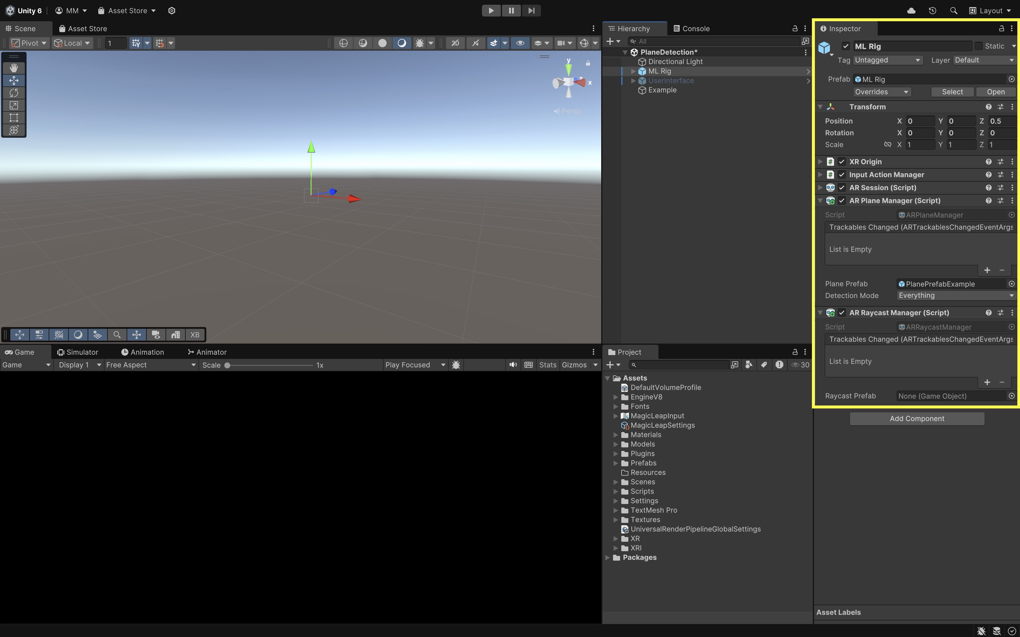
These managers enable plane detection (
ARPlaneManager) and raycasting support (ARRaycastManager) required for spatial understanding. TheExamplescript (PlaneExample.cs) ensures permissions are granted and activates plane detection on demand via the Bumper button, making plane data available at runtime. - Import and Add the Engine V8 Model:
- Import the provided
Engine V8.unitypackageinto Unity viaAssets > Import Package > Custom Package.... - In the
Hierarchy, create an empty GameObjectEngineSpawner. - Drag the
Engine V8prefab underEngineSpawner. - Disable the
Engine V8by default.

- Import the provided
- Create the Engine Placement Script:
- In
Assets > Scripts, create a new folder namedXRETutorialsto keep things organized. - In that folder, create
PlaceEngine.cs:
using UnityEngine; using UnityEngine.XR.ARFoundation; using UnityEngine.XR.ARSubsystems; using UnityEngine.XR.MagicLeap; public class PlaceEngineOnPlane : MonoBehaviour { public ARPlaneManager planeManager; public GameObject enginePrefab; public float offsetDistance = 1.0f; // meters in front of headset private MagicLeapInputs mlInputs; private MagicLeapInputs.ControllerActions controllerActions; private bool enginePlaced = false; void Start() { mlInputs = new MagicLeapInputs(); mlInputs.Enable(); controllerActions = new MagicLeapInputs.ControllerActions(mlInputs); controllerActions.Trigger.performed += _ => MoveEngineToPlane(); } private void MoveEngineToPlane() { if (enginePlaced || planeManager == null) return; foreach (var plane in planeManager.trackables) { if (plane.alignment == PlaneAlignment.HorizontalUp || plane.alignment == PlaneAlignment.HorizontalDown) { Vector3 planePosition = plane.transform.position; // Offset engine forward from headset Vector3 headsetPosition = Camera.main.transform.position; Vector3 headsetForward = Camera.main.transform.forward; Vector3 offset = headsetForward.normalized * offsetDistance; Vector3 targetPosition = planePosition + offset; enginePrefab.transform.position = targetPosition; // Align engine's rotation to plane's Y rotation float yRotation = plane.transform.eulerAngles.y; enginePrefab.transform.rotation = Quaternion.Euler(0, yRotation, 0); enginePrefab.SetActive(true); enginePlaced = true; Debug.Log( $"Engine placed at {targetPosition} " + $"with Y rotation {yRotation}" ); return; } } Debug.Log("No horizontal plane found."); } } - In
- Configure the Script:
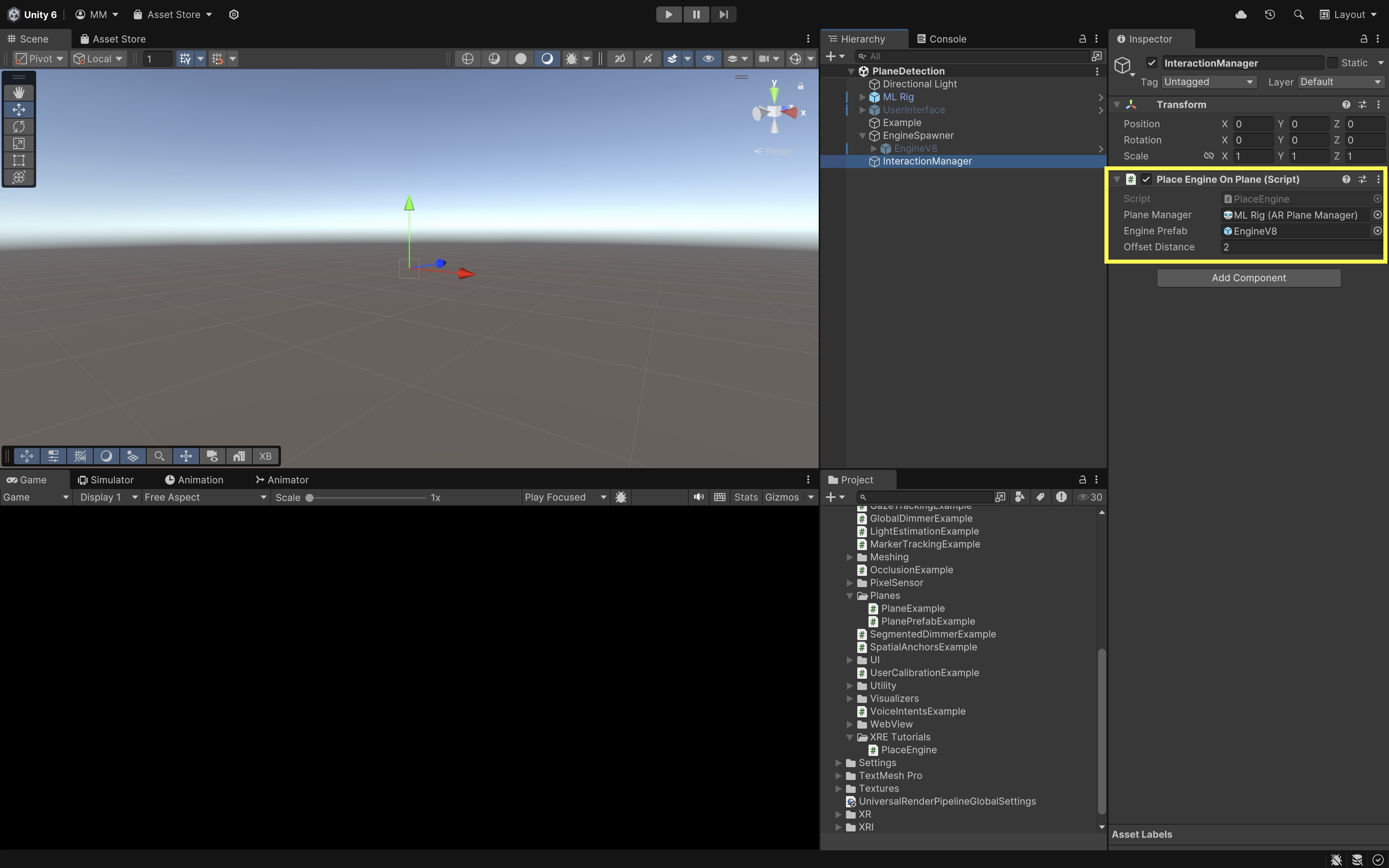
- Create an empty GameObject in the
Hierarchy. Name itInteractionManager. - Click
Add Componentand choosePlaceEngine. - Drag the
ML Rigfrom theHierarchyinto thePlane Managerfield of the script. - Drag your
Engine V8GameObject (underEngineSpawner) into theEngine Prefabfield. - Set
Offset Distanceto control how far in front of the headset the engine is placed on the plane (e.g., 1-2 meters).
- Create an empty GameObject in the
- Create the Touchpad Rotation Script:
- In the
Projectwindow, go toAssets > Scripts > XRETutorials. - Right click and create a new script. Name it
RotateWithTouchpad.cs.
using UnityEngine; using UnityEngine.XR.MagicLeap; public class RotateWithTouchpad : MonoBehaviour { public float rotationSpeed = 50f; private MagicLeapInputs mlInputs; private MagicLeapInputs.ControllerActions controllerActions; void Start() { mlInputs = new MagicLeapInputs(); mlInputs.Enable(); controllerActions = new MagicLeapInputs.ControllerActions(mlInputs); } void Update() { Vector2 touchpadInput = controllerActions.TouchpadPosition .ReadValue<Vector2>(); float horizontalInput = touchpadInput.x; if (Mathf.Abs(horizontalInput) > 0.1f) { transform.Rotate( Vector3.up, horizontalInput * rotationSpeed * Time.deltaTime, Space.World ); } } } - In the
- Configure the Script:
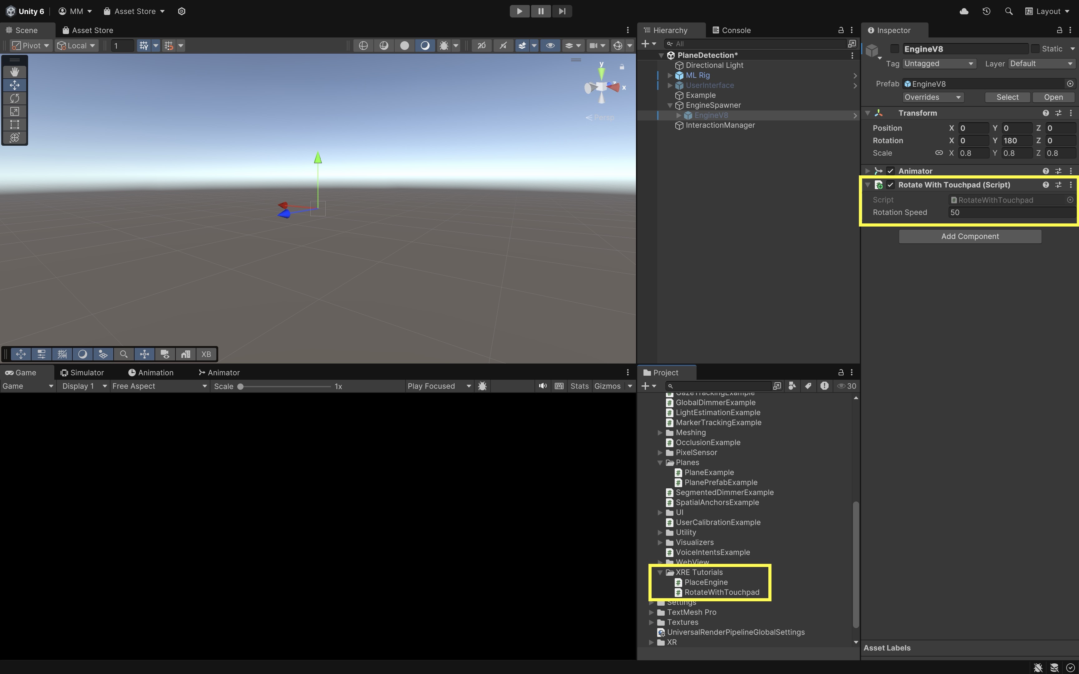
- Select the
Engine V8GameObject in theHierarchy. - Click
Add Componentand selectRotateWithTouchpad. - In the
Inspector, adjust theRotation Speedvalue to control how fast the engine rotates when swiping on the ML2 controller’s touchpad. For example, 50 degrees per second is a good starting point.
- Select the
- Deploy and Test the Behavior:
- Build and deploy the scene to your Magic Leap 2 device using the standard build process.
- On device, run the app.
- Press the Bumper button to start plane detection.
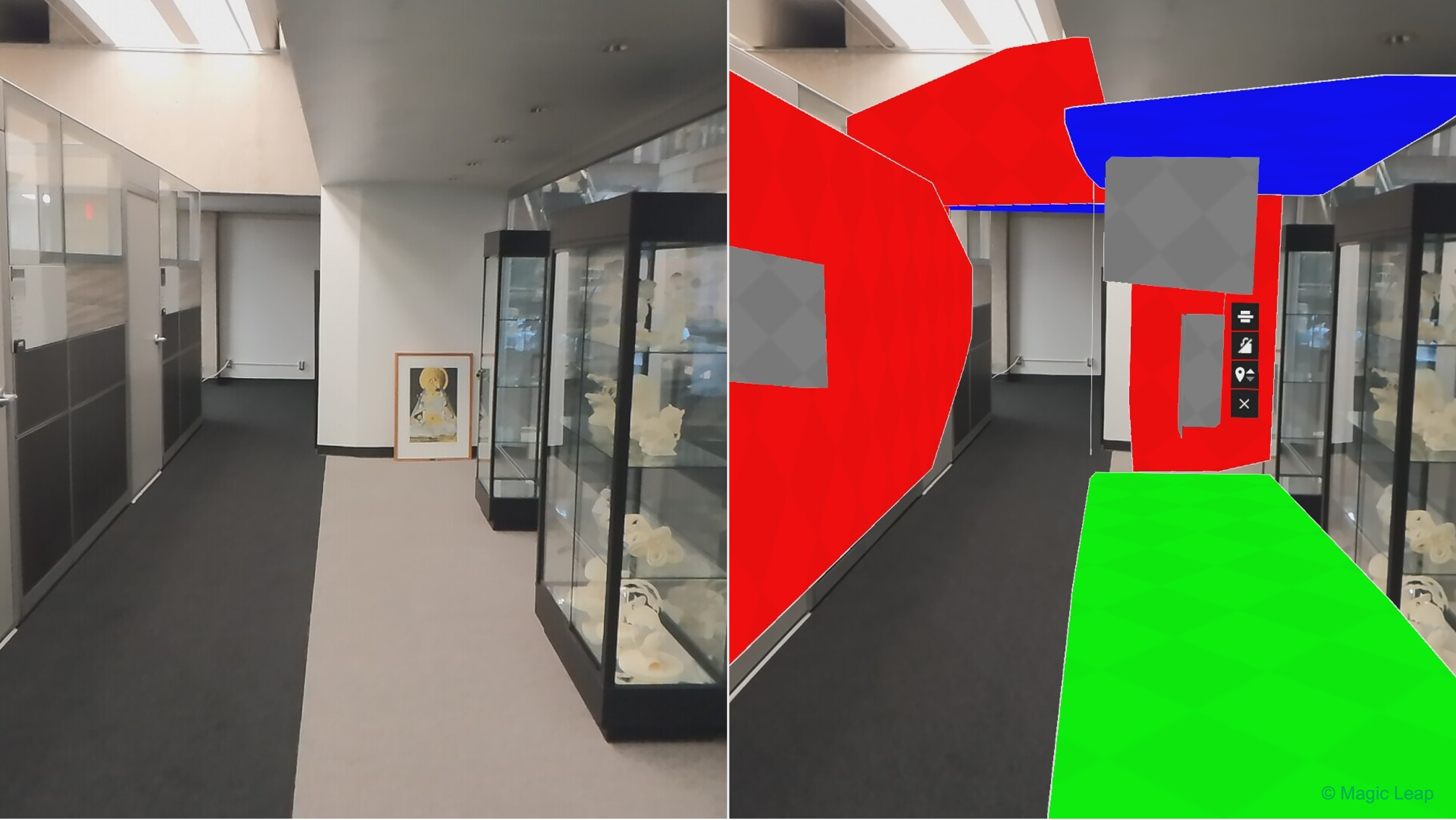
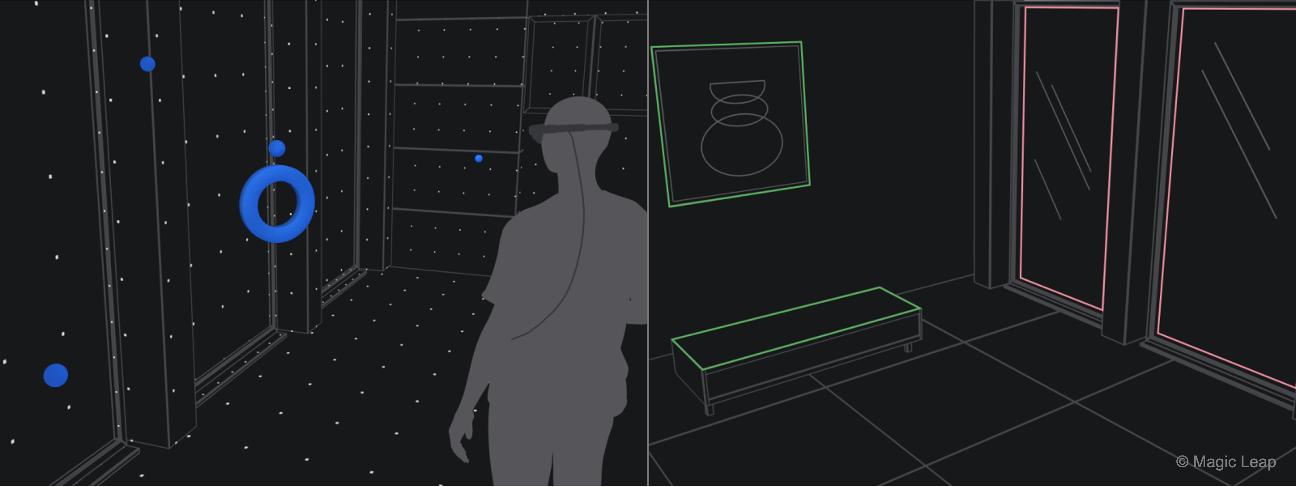
- As planes are detected, they will be color-coded based on classification:
- Green: Floor
- Red: Wall
- Blue: Ceiling
- Yellow: Table
- Gray: Other/Unclassified - Press the Trigger on the controller to place the engine model on the first detected horizontal plane, offset in front of the headset to avoid overlap. - Swipe left or right on the touchpad to rotate the engine around the Y-axis (vertical axis).
If all behaviors match, your plane detection, placement, and rotation interactions are working as expected!
Magic Leap Preliminaries
This tutorial walks you through the steps to develop and deploy a Hello World app to the Magic Leap 2—a popular see-through AR device—using Unity 6 LTS, AR Foundation, XR Interaction Toolkit, and OpenXR. We will create a new scene (ML101.unity) in your existing AR Foundation project, configure it for Magic Leap 2 with OpenXR, and deploy it to the headset.
Configure Magic Leap Hub
To build applications for Magic Leap 2, you need to install Magic Leap Hub 3, which manages SDKs, example projects, and essential tools like MRTK for Magic Leap.
- Install Magic Leap Hub 3:
- Visit the Magic Leap Developer Portal.
- Navigate to the Download: Magic Leap 2 Tools section.
- Download the Magic Leap Hub 3 installer for your operating system.
- Run the installer and complete the setup wizard.

- For Windows Users:
- Install the Microsoft Visual C++ Redistributables from the official Microsoft support page.
- Download the redistributable package for Visual Studio 2015, 2017, 2019, and 2022.
- Install the x64 version (typically required).
Failure to install these redistributables may cause the ML Hub or Application Simulator to fail.
- Install Magic Leap Packages for Unity and OpenXR:
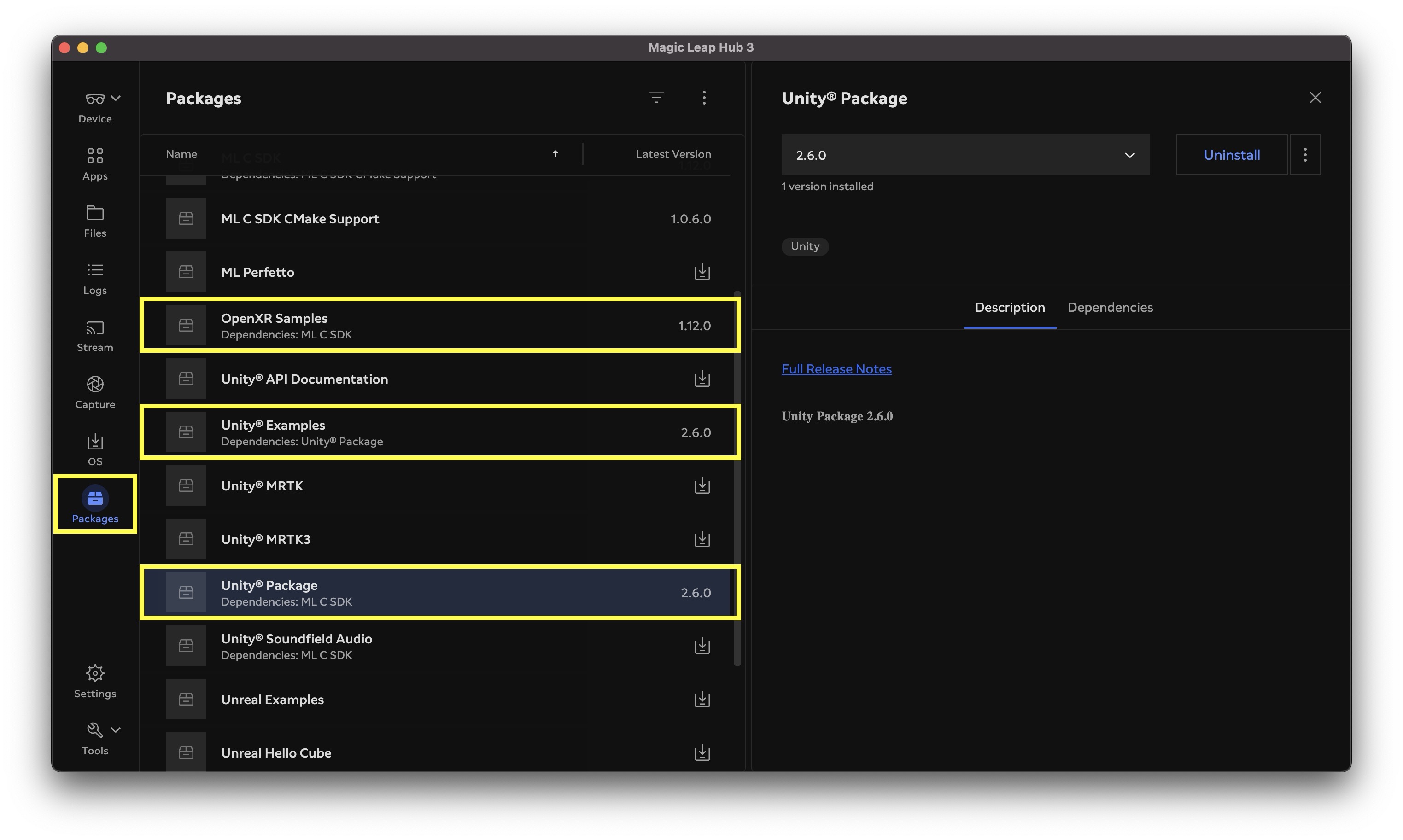
- Launch Magic Leap Hub 3.
- In the left sidebar, click Packages.
- In the Package Manager, install Unity® Package and OpenXR Samples. Optionally, install Unity® Examples.
Setup the Unity Project
The Magic Leap Examples Project is a Unity package showcasing sample scenes that demonstrate key Magic Leap 2 features using OpenXR, including interaction, spatial mapping, eye tracking, and more. It serves as a practical starting point for developers to learn and prototype XR applications on the Magic Leap platform. We will begin by using the Magic Leap Examples Project as a foundational starting point to understand core XR concepts and features, and gradually add custom capabilities and interactive experiences.
- Open the Installed Project:
- Navigate to
%USERPROFILE%\MagicLeap\tools\unity<SDK_VERSION>\MagicLeap_Examples. Replace<SDK_VERSION>with the version you installed via Magic Leap Hub 3. - Open Unity Hub.
- Click
Openand navigate to theMagicLeap_Examplesfolder. - Select the folder and click
Open. - To avoid modifying the original samples, go to
File > Save As (Project)(or manually copy the project folder). - Rename and save it, for example:
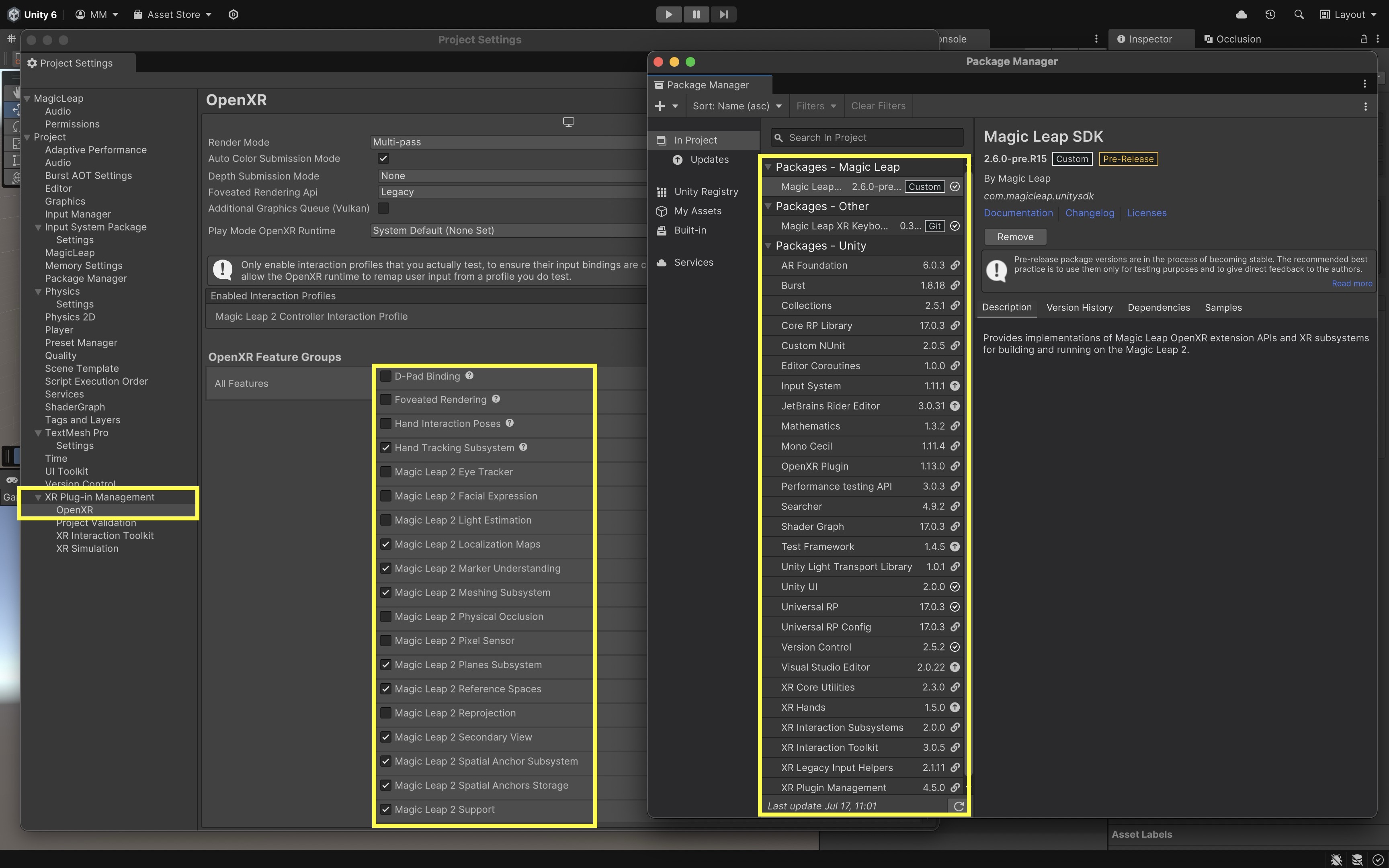
MagicLeapX. - Review the packages included in the preconfigured project via
Package Manageras well as the Magic Leap features underXR Plug-in Management > OpenXR Feature Group.
- Navigate to
- Explore the Built-In Example Scenes:
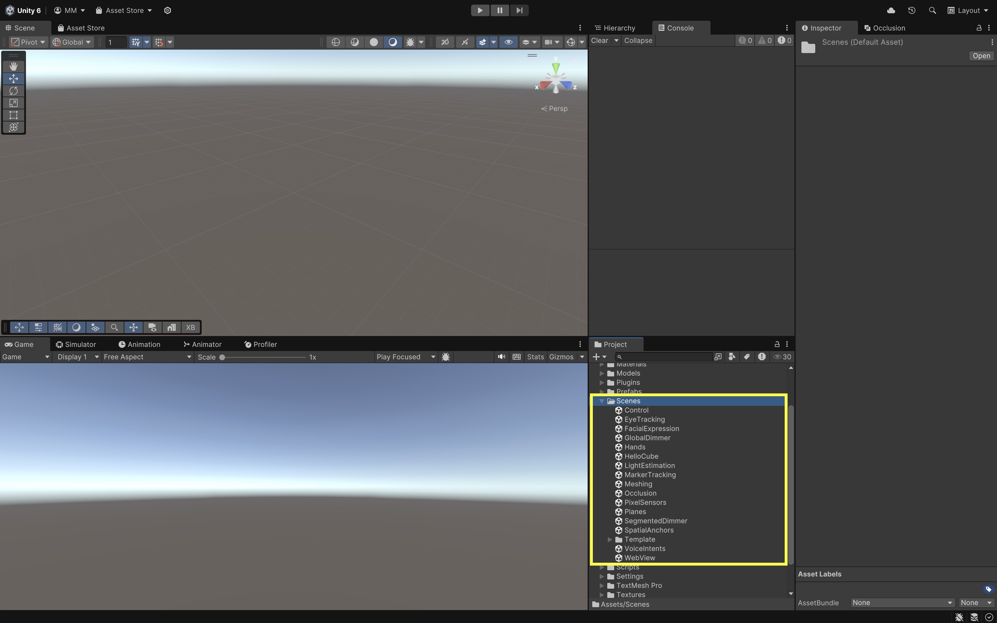
- Go to
Assets/Scenes/. - Open and explore the built in scenes, which demonstrate core Magic Leap 2 features and provide inspiration for your custom developments.
- Hello, Cube: A simple red cube floating in space — the default scene that serves as a “Hello World” for Magic Leap development.
- Control: Demonstrates best practices for interacting with the Control controller, including 6DoF tracking and connection status.
- Eye Tracking: Uses the Gaze Interaction profile to track your eye gaze and display feedback.
- Facial Expression: Showcases facial expression tracking capabilities when the necessary hardware and permissions are available.
- Global Dimmer: Demonstrates environmental dimming to reduce distractions around the user.
- Hands: Maps OpenXR hand gestures to Unity Input Actions using the XR Hands package. Tracks pinch gestures and joint data.
- Light Estimation: Captures ambient light data from the environment to adapt scene lighting dynamically.
- Marker Tracking: Detects and tracks visual markers in the environment for AR anchoring and content placement.
- Meshing: Visualizes the real-world mesh detected by the Magic Leap’s sensors, useful for spatial mapping.
- Planes: Detects surfaces (vertical, horizontal) and tags them semantically, such as floors, walls, ceilings, and tables.
- Pixel Sensor: Captures low-level pixel data for custom computer vision applications.
- Segmented Dimmer: Demonstrates segmented environmental dimming via alpha blending with specific rendering settings.
- Spatial Anchor: Provides spatial anchoring capabilities to pin virtual objects to real-world locations.
- Occlusion: Shows how to occlude virtual content with real-world geometry for more realistic integration.
- Voice Intents: Implements voice command recognition and intent handling within XR applications.
We will reference and build upon several of these examples throughout the course to create customized, interactive XR applications tailored for engineering contexts.
- Go to
- Explore the Scene and Hierarchy (HelloCube):
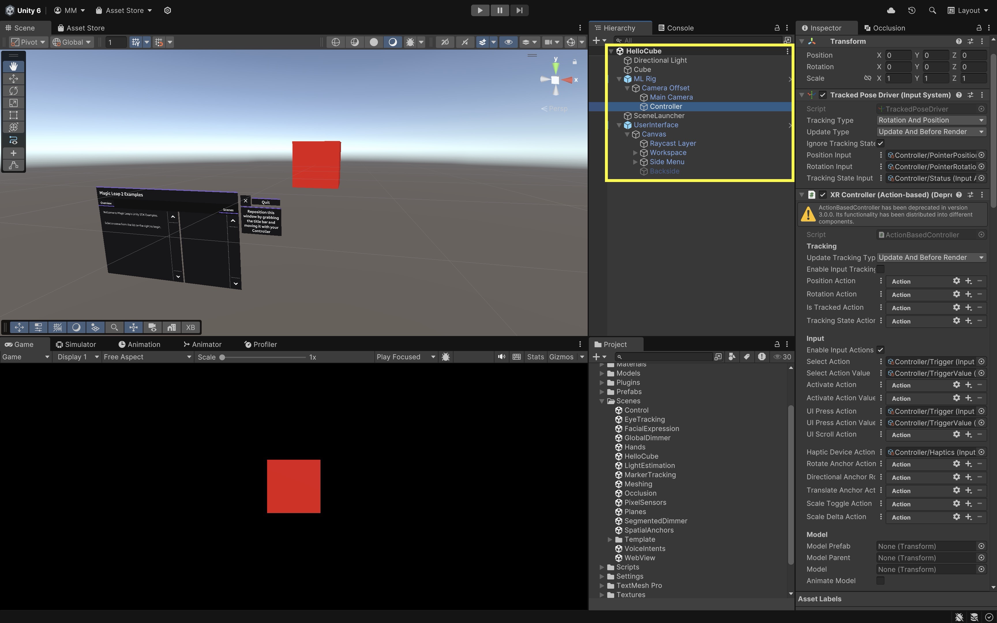
- Open the
HelloCube.unityscene and explore its key components in theHierarchywindow. Understanding these will help you extend and customize interactions later. ML Rig: This is the main rig responsible for tracking the user’s head and controller. It containsCamera Offset, which containsMain CameraandController.Main Camera: Represents the Magic Leap 2 user’s head position and orientation.Controller: Represents the physical Magic Leap single controller (Magic Leap 2 supports only one controller). Explore theXR Controller (Action-based)component on this object. It defines how controller input is mapped to interactions like grabbing or pointing. Review its other components such asXR Ray Interactor(for pointing and selecting UI or objects),Line Renderer(visualizes the interaction ray), andInput Action Manager(manages input bindings for the controller).UserInterface: This GameObject contains a canvas that holds menus, buttons, and instructional text. UI elements provide on-device guidance and allow interaction with the sample application.
- Open the
Deploy to Magic Leap 2
To run your Unity project on the Magic Leap 2 headset, you will need to configure Unity to build for the Android platform and ensure the headset is properly connected to your computer. Here are the essential steps to deploy your first app:
- Configure Build Profiles:
- In Unity, navigate to
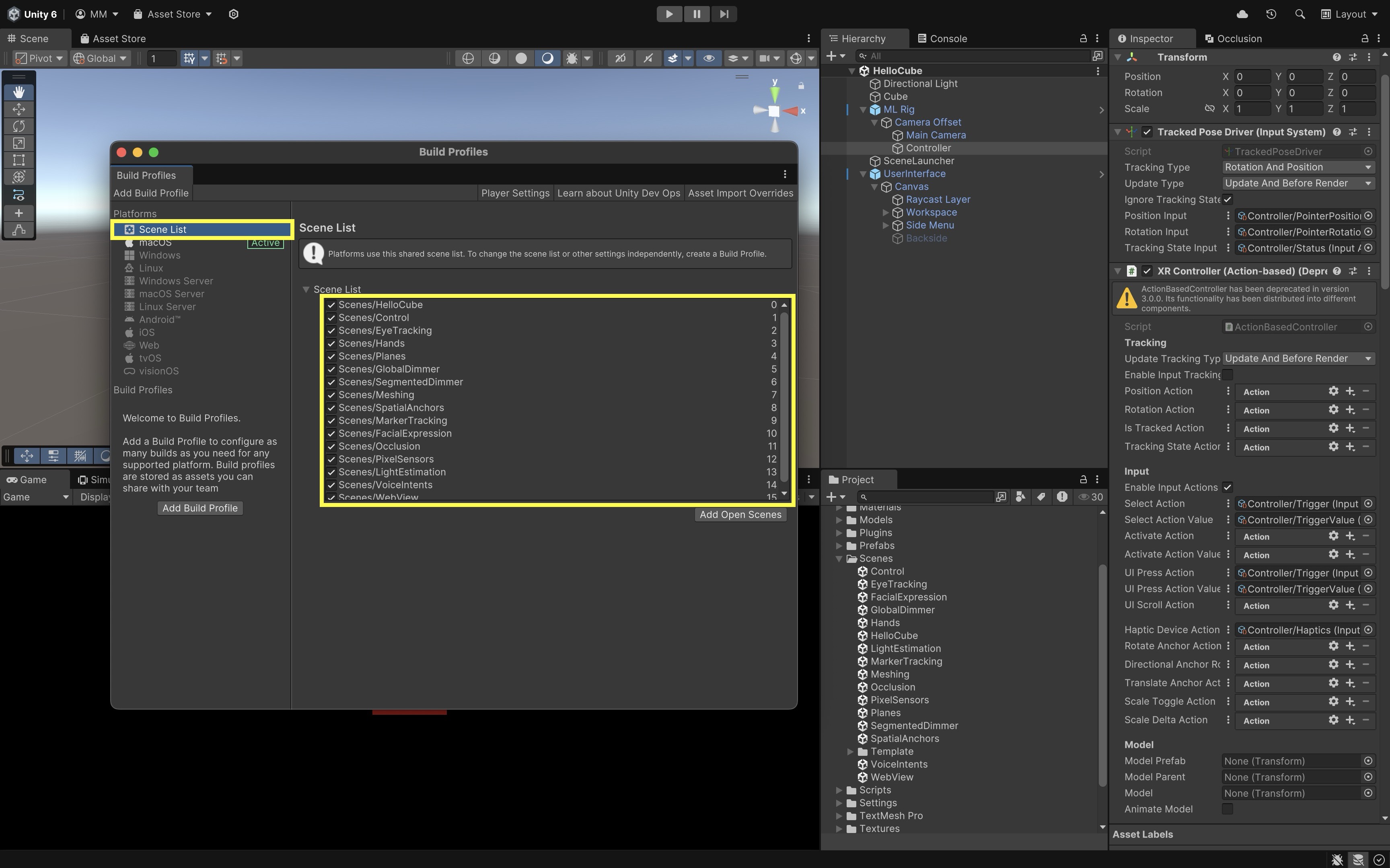
File > Build Profiles. - Go to
Scene Listand verify that all Magic Leap example scenes are selected.
- In Unity, navigate to
- Set Platform to Android:
- Select
Androidfrom the platform list. - If it is not already selected, click
Switch Platform. - If it is not installed, install it via Unity Hub.
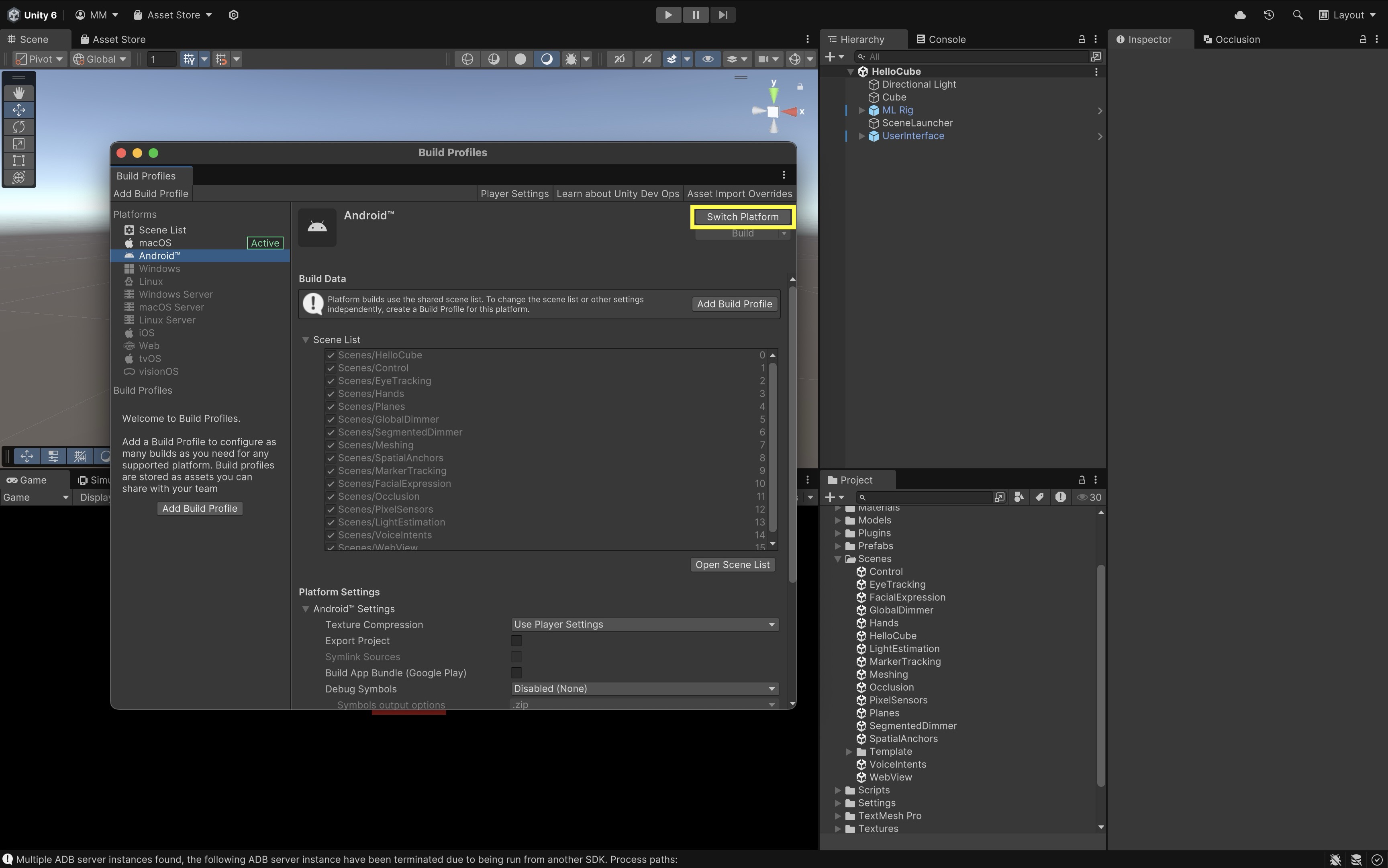
- Select
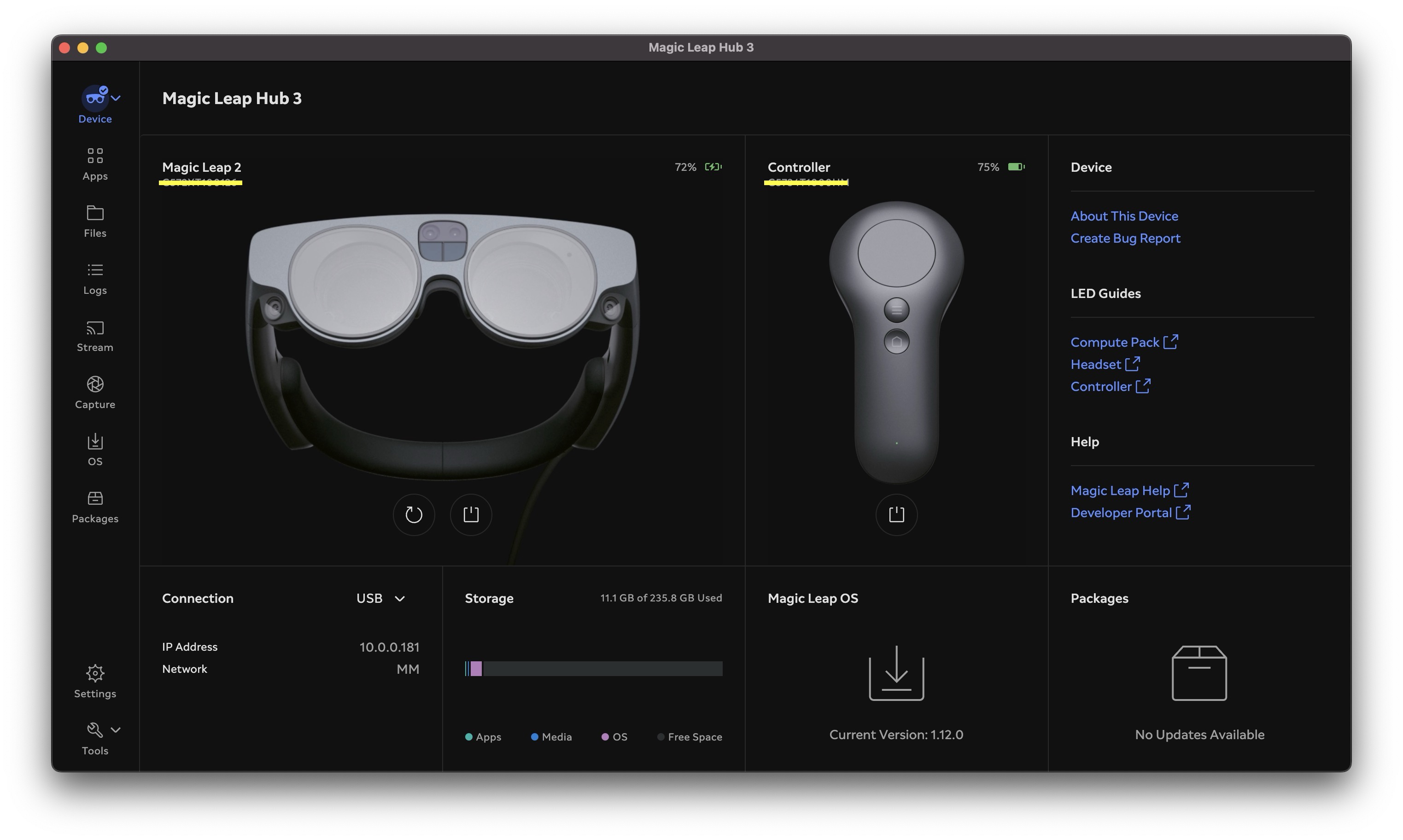
- Connect Your Magic Leap 2 Headset:
- Power on your Magic Leap 2 headset.
- Connect it to your computer using USB or set up ADB over WiFi via Magic Leap Hub 3.
- Open Magic Leap Hub 3 on your computer.
- Navigate to the Devices tab.
- Ensure your Magic Leap 2 appears as Connected. This confirms that the device is ready to receive a build.
- Select Run Device in Unity
- Return to Unity’s
Build Profilewindow. - Under
Run Device, choose your connected Magic Leap 2 from the dropdown list. - Click
Build and Runto compile the project and deploy it directly to the headset. - The app will automatically launch on the device after deployment.
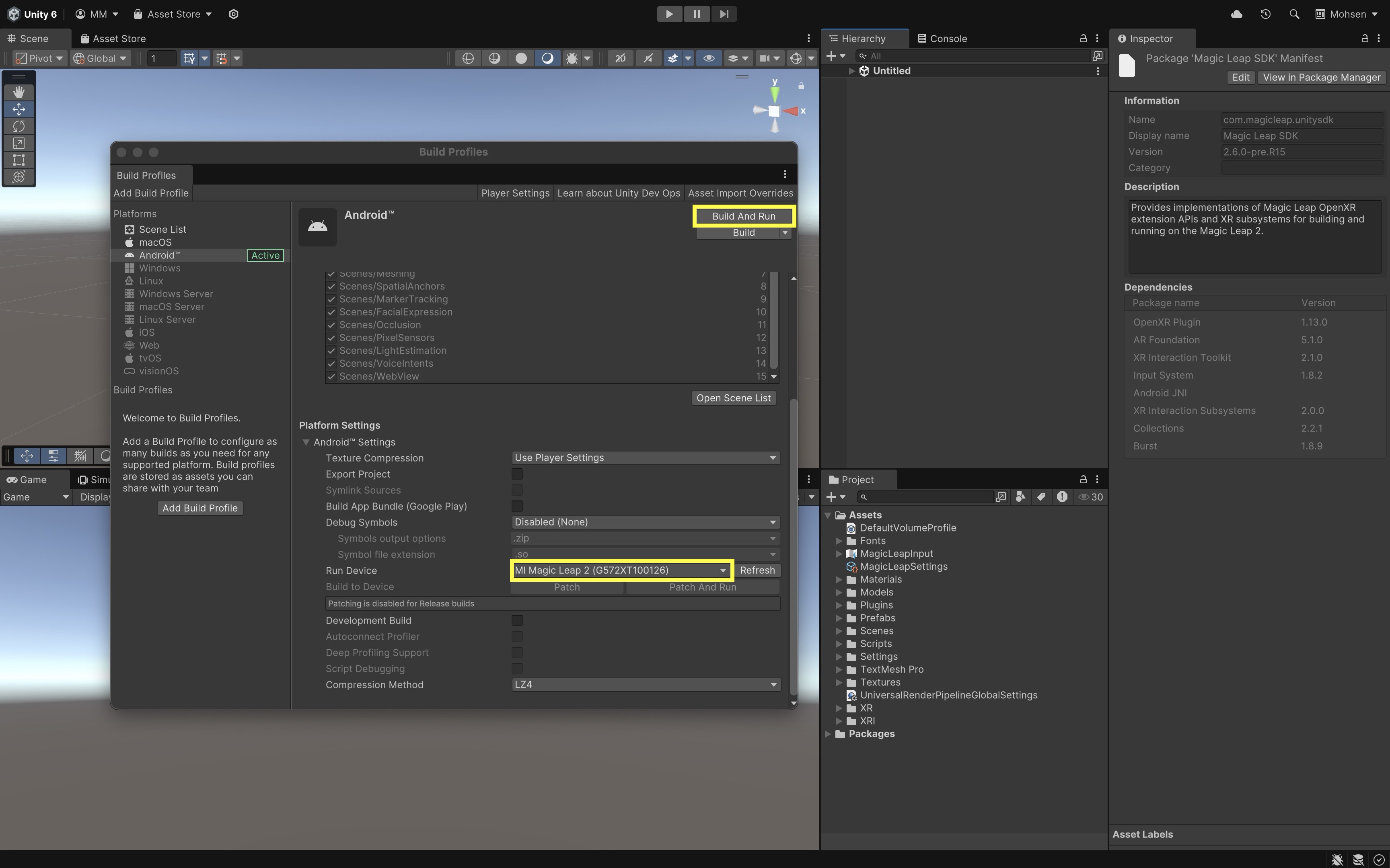
- Return to Unity’s
- Explore the Examples App:
- Launch the Magic Leap Examples app on your device.
- Select each example scene from the menu and explore its capabilities.
Meshing & Occlusion
Meshing and Occlusion are two foundational systems for spatially aware AR experiences. Together, they allow virtual objects to blend seamlessly into the user’s real-world environment — appearing behind real objects, resting on physical surfaces, and responding naturally to space. On devices such as the Meta Quest 3 and Magic Leap 2, these features are powered by real-time spatial mapping and depth sensing. Meshing reconstructs the physical environment as a dynamic 3D model, while Occlusion uses depth data to determine what parts of virtual content should be hidden behind real-world objects.
The result is immersive, physically consistent AR where the virtual and real coexist believably.
On wearable AR devices like Magic Leap 2 or Meta Quest 3, meshing is optimized for continuous, room-scale scanning and real-time responsiveness. These devices maintain persistent, large-scale meshes of the environment for spatial understanding. In contrast, handheld devices like iPhones or iPads with LiDAR produce denser, short-range meshes for precise but smaller-scale occlusion and interaction.
Core Concepts
-
Occlusion: Determines which virtual objects should be visible or hidden based on real-world depth.
This allows digital content to appear naturally behind real objects. -
Meshing: Continuously scans and reconstructs the user’s surroundings into a dynamic 3D mesh.
Unlike plane detection, meshing captures complex and irregular surfaces — walls, furniture, and objects — creating a full spatial map. -
AROcclusionManager: A Unity AR Foundation component that manages environment and human depth textures, enabling occlusion between real and virtual objects. -
ARMeshManager: Manages the detection and updating of real-world meshes in real time.
It divides the environment into mesh chunks that update as the user moves, ensuring that spatial mapping stays accurate. -
Mesh Prefab: Defines how each generated mesh chunk is rendered and how it interacts with physics.
By assigning an AR → Occlusion material, these meshes become invisible occluders that block virtual objects behind them. -
Mesh Collider: Allows virtual objects to physically interact with the reconstructed geometry, preventing them from passing through real-world surfaces. -
Spatial Mapping Permission (Magic Leap): Required for scanning the environment; ensures user privacy and controls access to spatial data.
-
Physics.Raycast: A Unity method used to detect intersections with real-world geometry — essential for features like object placement, navigation, or obstacle avoidance.
Meta Quest 3 Implementation
In passthrough AR on Meta Quest 3, occlusion makes virtual objects disappear naturally behind real-world surfaces, while meshing lets your app understand and reconstruct the 3D geometry of the environment. Combined, these features create realistic, spatially aware AR experiences using AR Foundation and OpenXR.
Occlusion Setup
- Add the AR Occlusion Manager:
- On your
Main Camera, add theAR Occlusion Managercomponent. - This enables environment depth data, allowing real surfaces (like tables or floors) to hide virtual objects based on the headset’s spatial awareness.
- You can leave the defaults as they are or choose a higher-quality
Environment Depth Modeif desired.
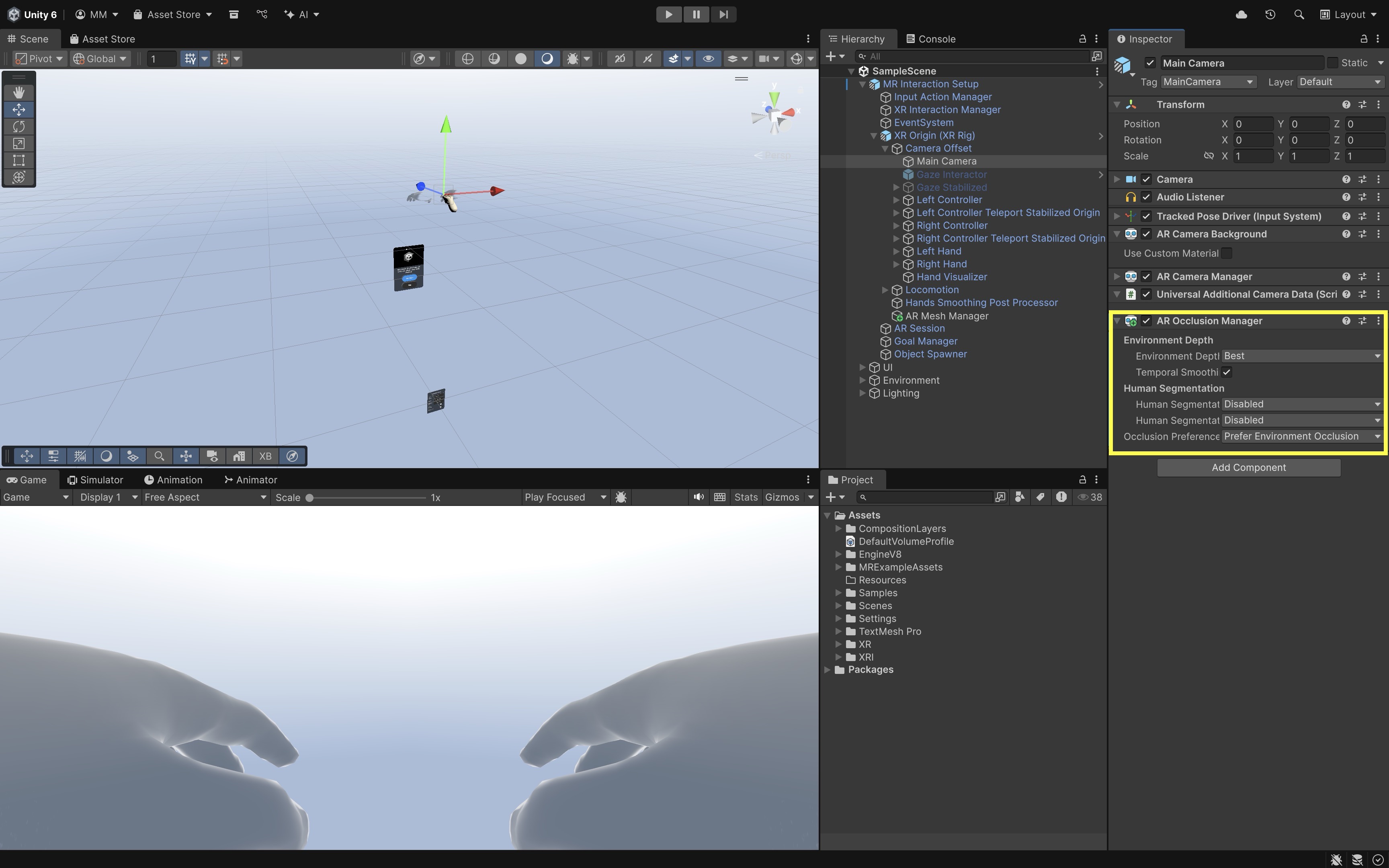
- On your
- Create an Occlusion Material:
- In your
Assetsfolder, create a newMaterialand name itOcclusion. - In the
Shaderdropdown, selectAR > Occlusion. - This shader is invisible but writes to the depth buffer, which means it hides (occludes) virtual objects behind it.
- In your
- Apply the Occlusion Material to AR Planes
- Select your
AR Planeprefab. - In the
Mesh Renderer, assign the newOcclusionmaterial. - This turns your detected real-world planes (like floors, tables, and walls) into invisible occluders that hide any virtual objects placed behind them.
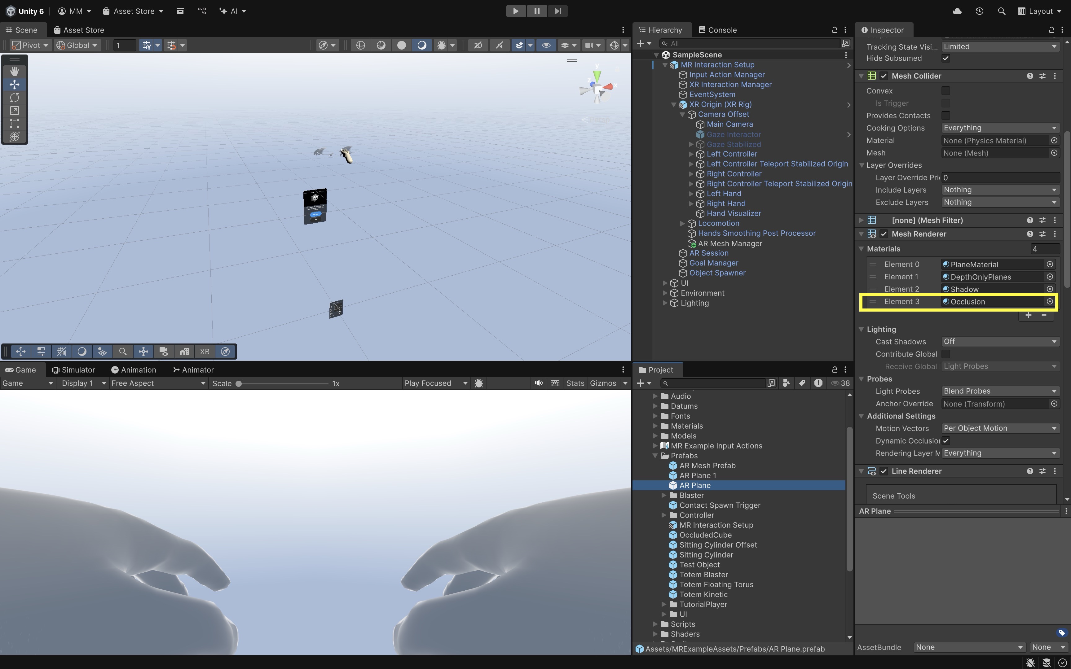
- Select your
- Build and Test:
- Deploy to your Meta Quest 3.
- Move around your environment and observe that detected planes will occlude virtual content.
- At this point, you’ve achieved basic occlusion using AR planes and the
AR Occlusion Manager.
Meshing Setup
While plane detection handles large flat surfaces, meshing captures the entire environment—including irregular shapes like furniture, walls, and objects — allowing even more precise occlusion.
- Add the
AR Mesh Manager:- Under your
XR Origin, add anAR Mesh Managercomponent. - This component dynamically generates 3D meshes that represent your real-world surroundings in real time.
- Under your
- Create a Mesh Prefab:
- In your
Assets, create an empty prefab calledMeshPrefab. - Add
Mesh Filter,Mesh Renderer,Mesh Collider(if you want physical interactions). - Assign two materials to the
Mesh Renderer:
- Material 1: any colored URP/Lit material (for debugging; makes the mesh visible)
- Material 2: your Occlusion material (so the mesh also hides virtual objects) - Save the prefab.
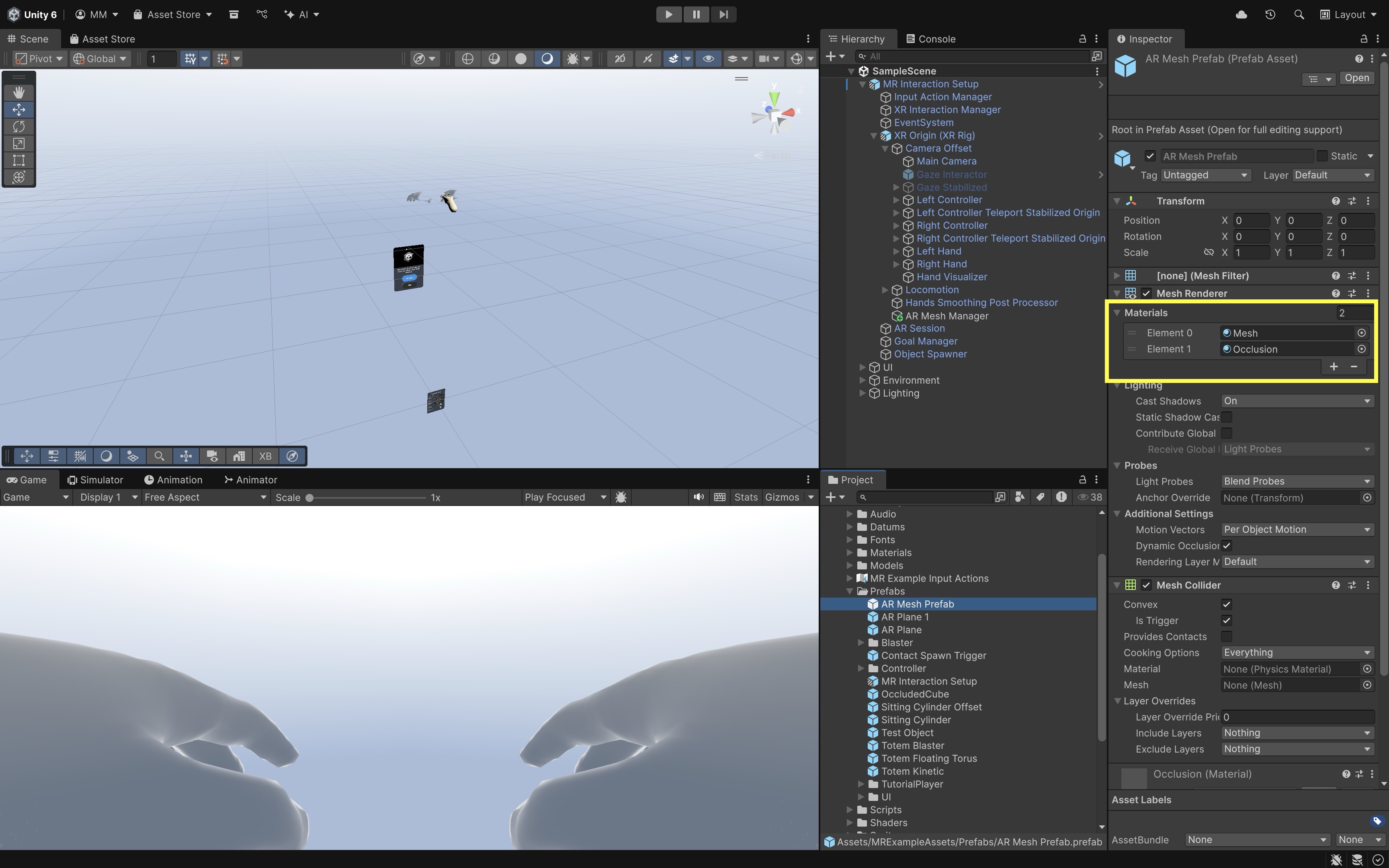
- In your
- Assign the Mesh Prefab:
- In your
AR Mesh Managercomponent, setMesh Prefabto your newly createdMeshPrefab. - Adjust
Densityto control how detailed the generated mesh will be.
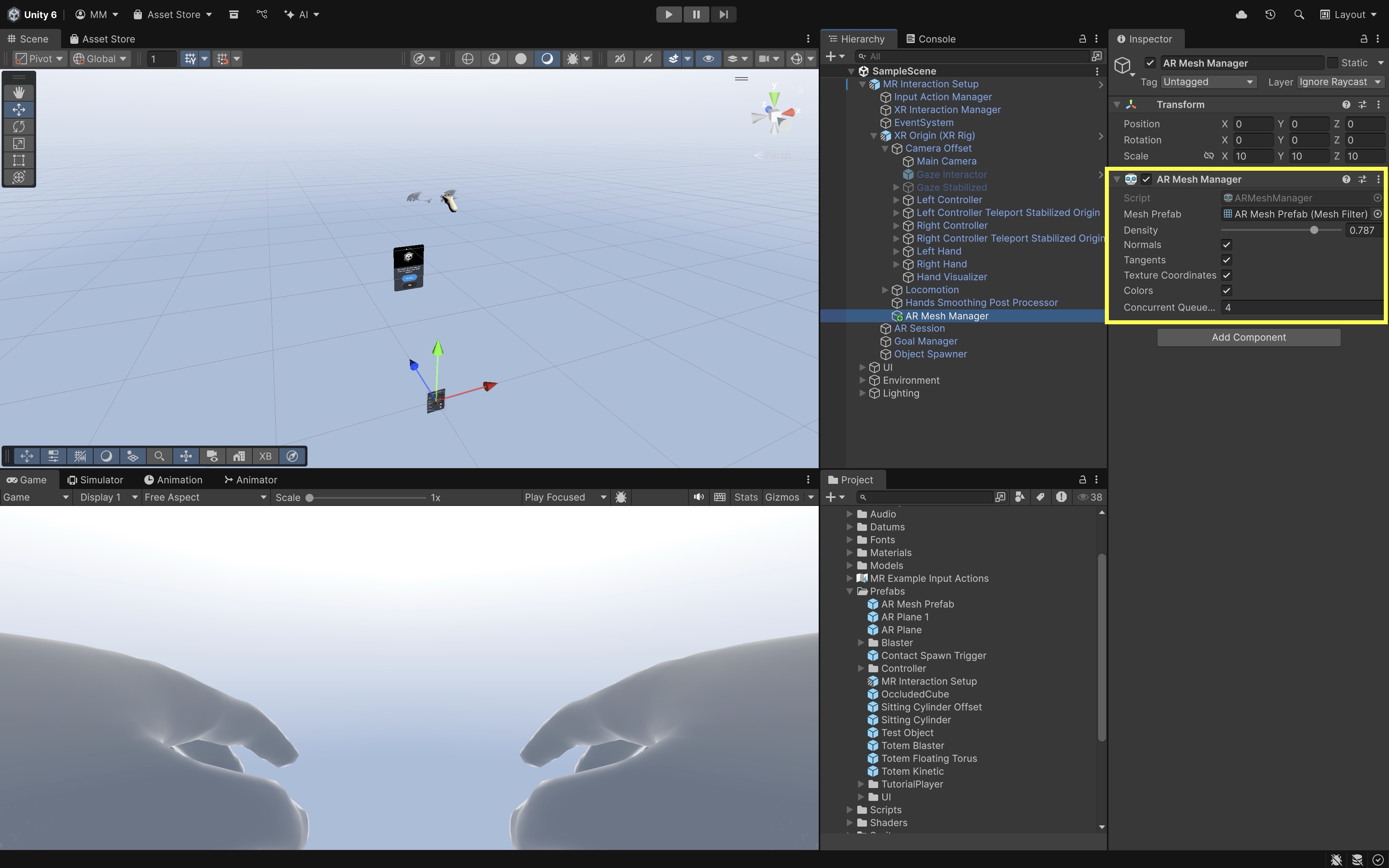
- In your
- Deploy and Test Meshing:
- Build and deploy again to your Meta Quest 3.
- The headset will start generating colored debug meshes (if you used a visible material).
- As these meshes appear, they will automatically occlude virtual objects — not just flat planes but all real-world shapes.
- Now, your entire environment acts as an invisible occluder, allowing virtual content to interact realistically with the physical world.
Optional Cleanup for Production: Once you’ve confirmed that meshing and occlusion work, remove the debug-colored material from your mesh prefab. Keep only the
Occlusionmaterial for invisible, depth-only rendering. Disable Cast Shadows and Receive Shadows on the mesh for optimal performance.
Magic Leap 2 Implementation
We will build a tutorial where the Magic Leap 2 device scans the surrounding space and generates meshes. A virtual drone is spawned in front of the user. Using the Magic Leap controller, the user can move the drone in 3D space while respecting the scanned environment. The drone stops moving when it approaches a real-world mesh, preventing it from passing through physical structures.
- Duplicate the Meshing Scene:
- Open the
Meshing.unityscene from the Magic Leap examples project. - Save it as
Assets > Scenes > XRE Tutorials > Meshing.unity.
- Open the
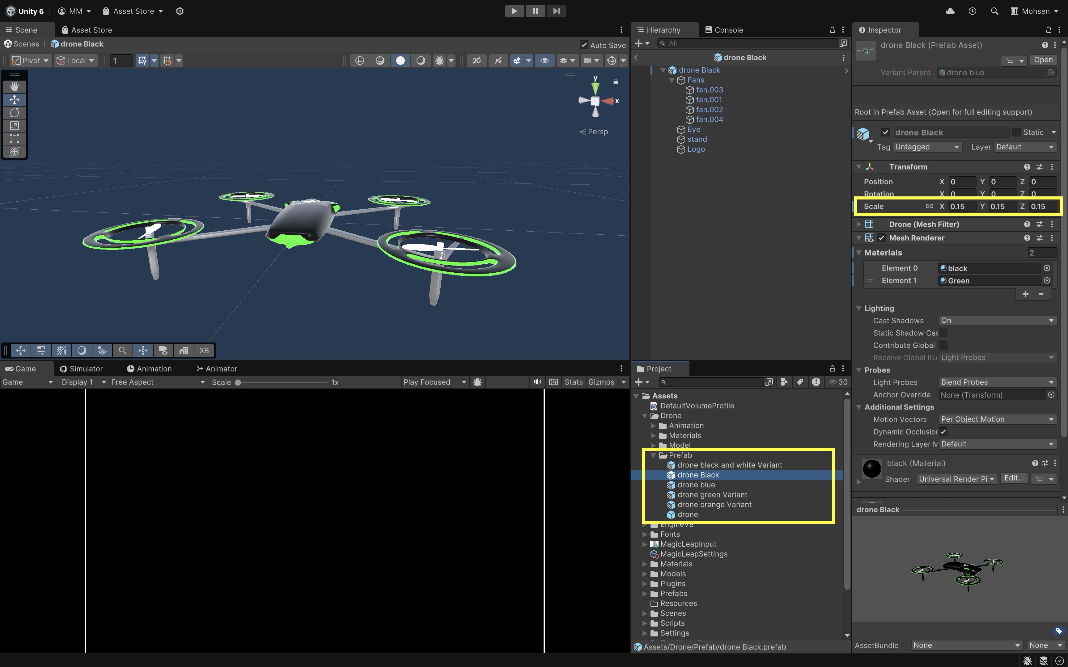
- Import the Drone Package:
- Right-click in the
Projectwindow. - Select
Import Package > Custom Package. - Import the provided
Drone.unitypackage. - You will now see multiple
Droneprefabs in theProjectwindow. - The drone models are slightly larger than normal. Open and rescale them in prefab mode (e.g., to 15%).
- Right-click in the
- Place the Drone in Front of the User:
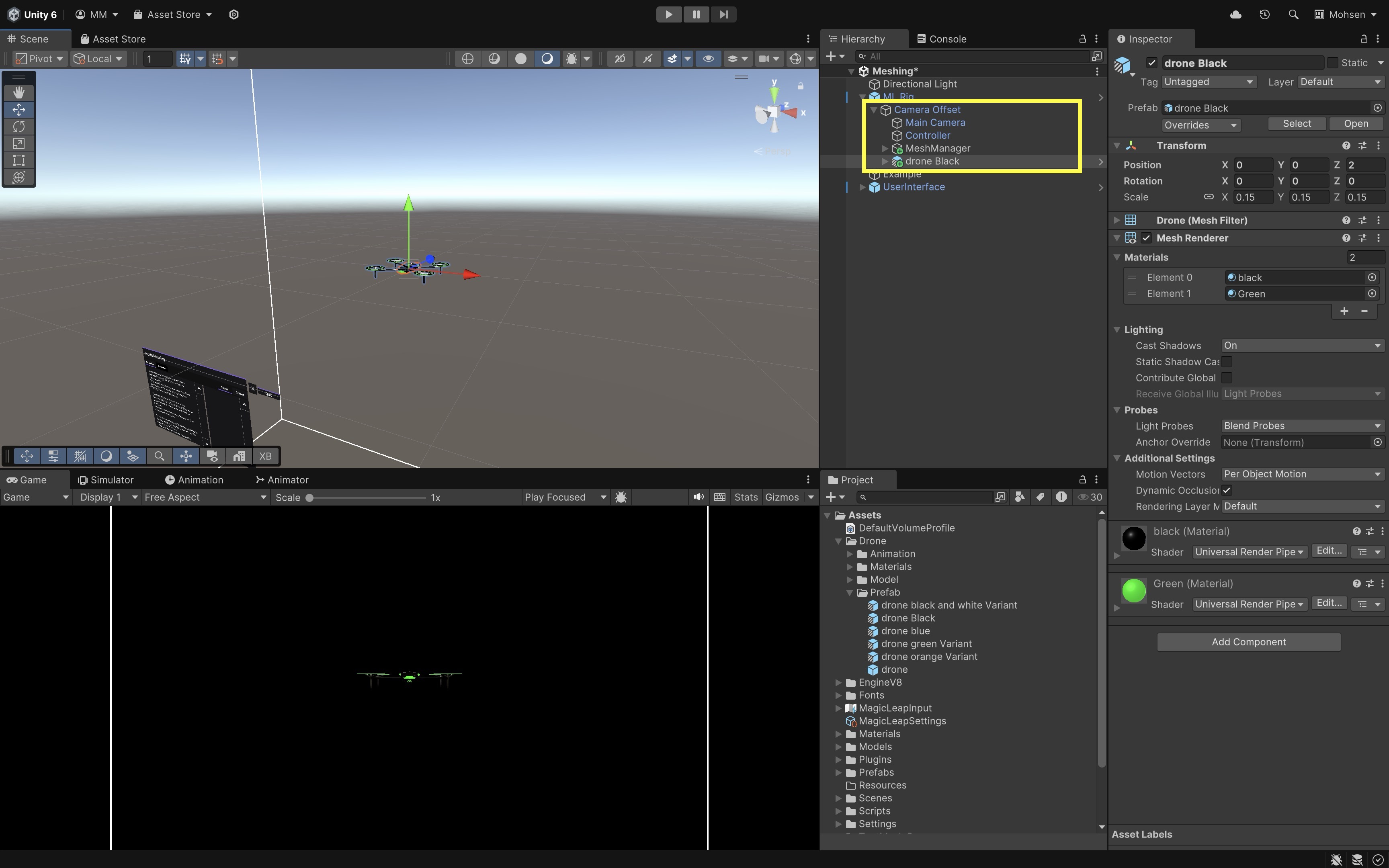
- In the
Hierarchy, locateML Rig > Camera Offset > Main Camera. - Drag a
Droneprefab into the scene (as a root object, not a child of the camera). - Reset its transform, then set its
PositiontoX: 0,Y: 0.5,Z: 2. This places the drone approximately 2 meters ahead and slightly above the user’s initial position.
- In the
- Add a DroneController Script:
- Go to
Assets > Scripts > XRE Tutorials. - Create a new
DroneController.csscript and drag it onto theDroneprefab in the scene. This script enables the drone to move in 3D space based on controller input while preventing it from passing through scanned environment meshes by using raycasting.
using UnityEngine; using UnityEngine.XR; using UnityEngine.XR.ARFoundation; using System.Collections.Generic; public class DroneController : MonoBehaviour { public float moveSpeed = 0.5f; public float checkDistance = 0.5f; private Transform droneTransform; private Camera mainCamera; private ARMeshManager meshManager; private InputDevice controllerDevice; private bool moveUpMode = true; // Toggle for up/down private bool triggerHeld = false; private void Start() { droneTransform = transform; mainCamera = Camera.main; meshManager = FindObjectOfType<ARMeshManager>(); var inputDevices = new List<InputDevice>(); InputDevices.GetDevicesAtXRNode( XRNode.RightHand, inputDevices ); if (inputDevices.Count > 0) { controllerDevice = inputDevices[0]; Debug.Log( "Magic Leap controller detected: " + controllerDevice.name ); } else { Debug.LogError("No controller device found."); } } private void Update() { if (!controllerDevice.isValid) return; Vector2 axisInput = Vector2.zero; controllerDevice.TryGetFeatureValue( CommonUsages.primary2DAxis, out axisInput ); Vector3 direction = (mainCamera.transform.right * axisInput.x) + (mainCamera.transform.forward * axisInput.y); // Check if trigger is pressed bool triggerPressed; controllerDevice.TryGetFeatureValue( CommonUsages.triggerButton, out triggerPressed ); if (triggerPressed && !triggerHeld) { // Toggle between up and down when trigger is pressed down moveUpMode = !moveUpMode; triggerHeld = true; Debug.Log( "Toggled movement mode: " + (moveUpMode ? "Move Up" : "Move Down") ); } else if (!triggerPressed) { triggerHeld = false; } if (triggerPressed) { direction += moveUpMode ? Vector3.up : Vector3.down; } if (direction != Vector3.zero) TryMove(direction.normalized); } private void TryMove(Vector3 direction) { if (!Physics.Raycast( droneTransform.position, direction, out RaycastHit hit, checkDistance )) { droneTransform.position += direction * moveSpeed * Time.deltaTime; } else { Debug.Log( "Movement blocked by environment mesh." ); } } } - Go to
- Confirm Mesh Prefab Configuration:
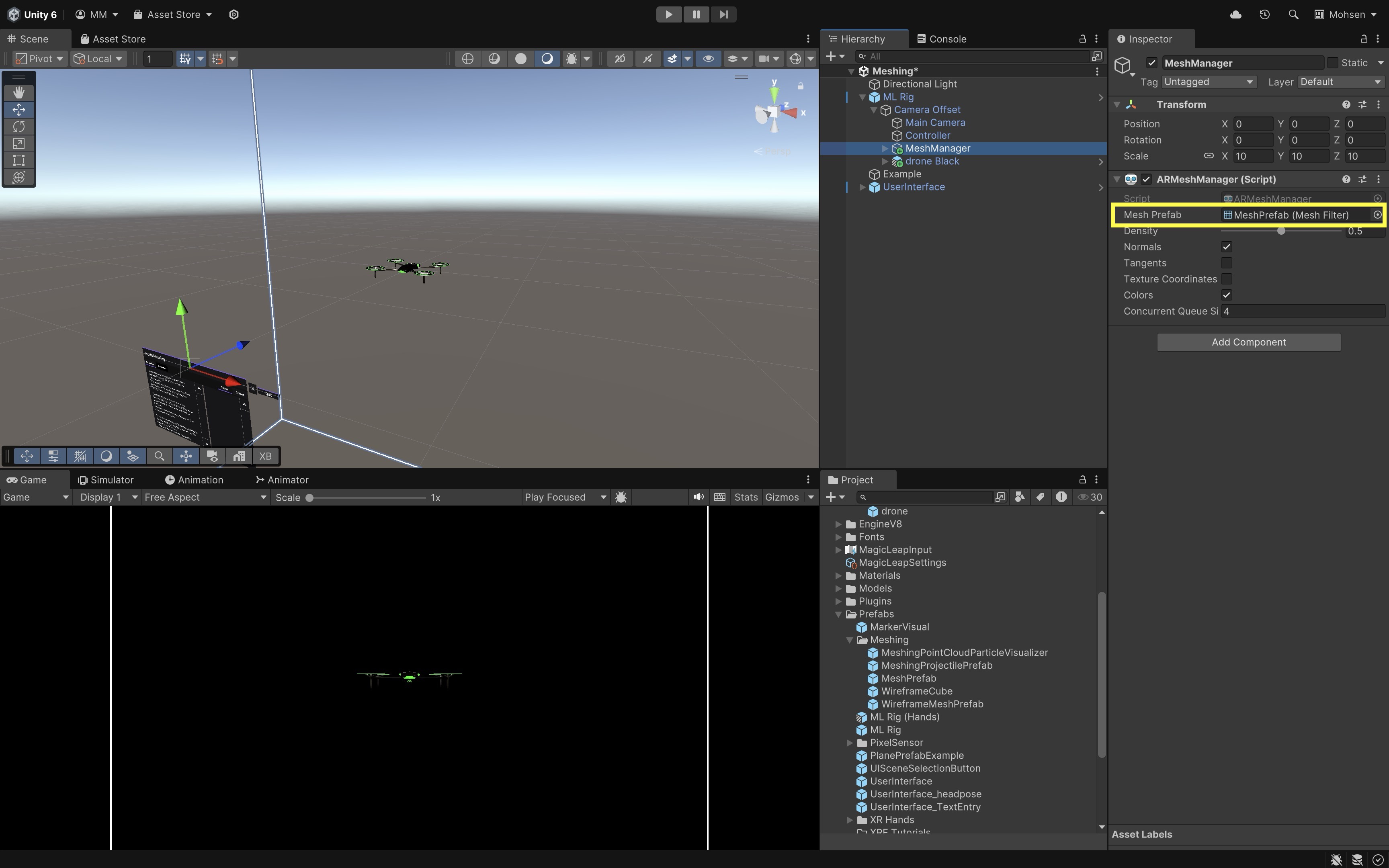
- In the
ARMeshManager, locate theMesh Prefab. - Confirm that it has a
MeshRendererwith a visible material and aMeshColliderattached for collision detection. - If the
MeshCollideris missing, open theMesh Prefab, and add aMeshCollidercomponent.
- In the
- Deploy and Test the Behavior:
- Build and deploy the
Meshing.unityscene to your Magic Leap 2 device using the standard build process. - On device, run the app and allow it to scan the environment.
- The surrounding environment will be dynamically reconstructed into a 3D mesh.
- A drone will appear approximately 2 meters in front of you.
- Use the touchpad/thumbstick to move the drone forward, backward, left, and right relative to your viewpoint.
- Press and hold the Trigger button to move the drone vertically — either up or down depending on the current mode.
- Tap the Trigger button to toggle between move up and move down modes.
- If the drone approaches any scanned mesh, it will stop moving in that direction to avoid collision.
- Build and deploy the
If all behaviors function as described, you have successfully integrated real-time meshing with spatially aware drone navigation!
Spatial Audio
Traditionally, audio is captured and played back in stereo (left/right), providing only limited directional cues. Spatial audio expands on this by simulating how sound behaves in three dimensions, taking into account the listener’s position, head orientation, and environment. The result is sound that feels anchored in space — letting users perceive whether a sound is coming from in front, behind, above, or below. Spatial audio is a cornerstone of wearable AR experiences on wearable devices such as the Meta Quest 3 and Magic Leap 2. Both platforms use head tracking and spatial mapping to place sounds naturally within the user’s surroundings, enhancing realism and interaction fidelity.
Benefits of Spatial Audio
-
Immersion: Spatial audio enhances presence by making sound behave naturally within 3D space. When audio reacts to your movement and head rotation, virtual objects feel physically present — both visually and acoustically.
-
Intuitive Interaction: Sound acts as a subtle guide for user attention. For example, an object can emit a tone from behind you, prompting you to turn toward it without any visual cue.
-
Accessibility: Spatial cues help users track object positions even without visual feedback, improving inclusivity and safety in low-visibility or accessibility-focused applications.
-
Enhanced Feedback Loops: Pairing visual and spatial audio cues creates richer feedback. A virtual drone, for example, sounds louder and shifts positionally as it approaches, reinforcing the illusion of real motion.
-
Training and Simulation: Spatialized sound can replicate real-world acoustic conditions for industrial, medical, or emergency training — such as localizing machinery noise or alarms in complex environments.
On Meta Quest 3 and Magic Leap 2, spatial audio is processed in real time based on head position and environmental geometry. For example, a flying drone’s propeller noise dynamically shifts and pans as it moves — louder when it’s close, quieter as it retreats, and naturally changing direction as it circles around you.
Core Concepts
-
Spatial Audio Engine / Plugin: Both Meta Quest and Magic Leap provide spatialization systems integrated with Unity’s audio engine. On Quest, Unity typically uses the Oculus Spatializer. On Magic Leap, the Soundfield (MSA) Spatializer provides advanced 3D sound rendering.
-
Spatializer Plugin: The audio spatializer processes how sounds are perceived in 3D space, including direction, distance, and environmental effects like reflections and attenuation.
-
Ambisonic Decoder: Decodes ambisonic audio formats to produce immersive 360° ambient sound fields — useful for environmental ambience or scene-based sound design.
- Listener Component: Acts as the user’s “ears” in the virtual world — usually attached to the camera.
- On Quest, this is the Audio Listener component.
- On Magic Leap, the
MLListenerprovides enhanced head-tracked spatial perception.
- Spatial Sound Source Component: Each 3D audio source should have a positional audio component that defines how sound radiates and fades with distance.
- On Quest, use Unity’s Audio Source with spatialization enabled.
- On Magic Leap, use
MLPointSourcefor detailed control over directivity and gain.
Spatial audio brings depth and realism to AR and MR experiences by allowing users to hear where sounds come from in their physical space. On Meta Quest 3, it enhances passthrough AR scenes by anchoring sound to virtual content within the user’s actual environment. On Magic Leap 2, it enables precise, low-latency 3D soundscapes that adapt to user motion and environment geometry.
Magic Leap 2 Implementation
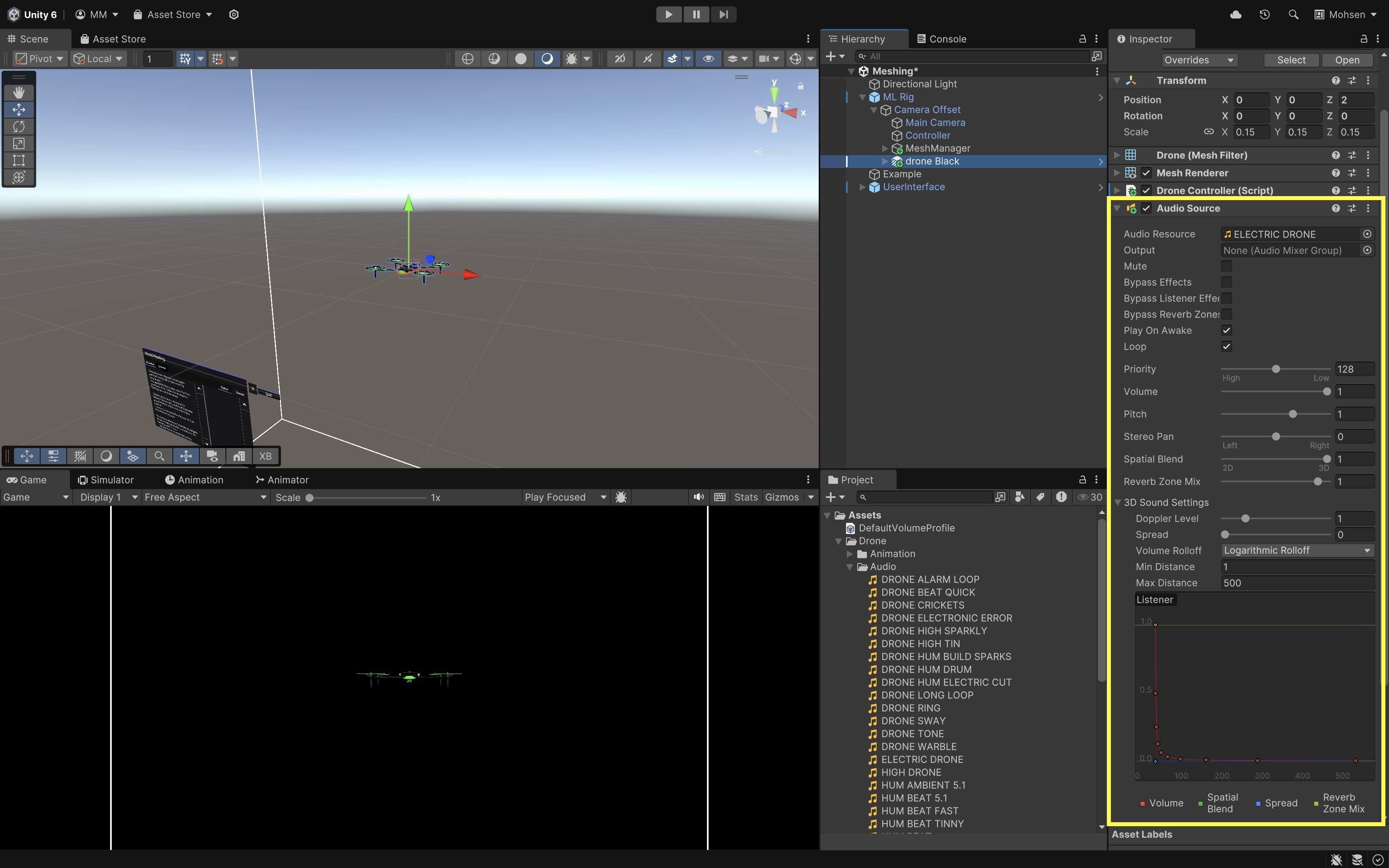
To bring the drone to life audibly, we will add 3D spatial audio that simulates the sound of its propellers in space. This setup ensures that as the drone moves closer or farther from the user, the audio dynamically reflects its position and movement.
- Add an Audio Source to the Drone:
- Select the
DroneGameObject in theMeshing.unityscene. - Add an
Audio Sourcecomponent. - Assign a looping drone sound clip (e.g.,
Assets > Drone > Audio > ELECTRIC DRONE) toAudio Resource. - Enable
Play On Awake. - Enable
Loop. - Set
Spatial Blendto1 (3D). - Choose
Logarithmic Rollofffor natural distance-based fading. - Adjust
Min DistanceandMax Distanceto define how close the sound is loud and how far it fades out.
- Select the
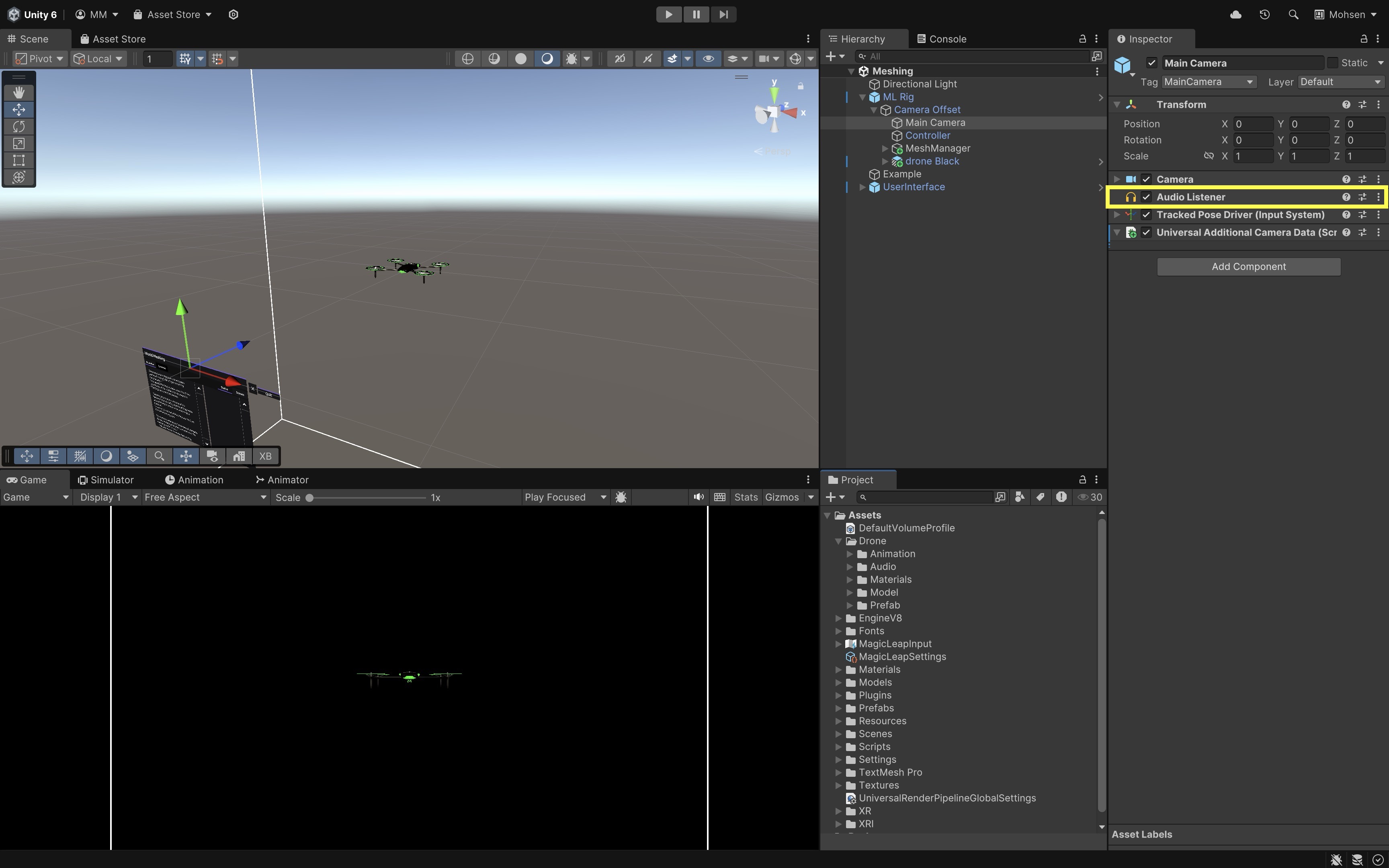
- Confirm the Audio Listener:
- Verify that the
Main Camera(underML Rig > Camera Offset > Main Camera) has theAudio Listenercomponent. - This is typically already present by default. If missing, add
Audio Listener.
- Verify that the
- Deploy and Test the Behavior
- Build and deploy the
Meshing.unityscene to your Magic Leap 2 device. - Run the app and let the environment scan complete.
- The drone will spawn approximately 2 meters ahead.
- Move the drone.
- As the drone approaches you, the propeller sound should get louder.
- As the drone moves away, the sound should naturally fade.
- Move around the drone in space—its sound should pan left, right, front, and back based on your position.
- Build and deploy the
Consider adjusting the
Max Distanceon theAudio Sourceto control how far the sound can be heard, modifyingSpreadto control how directional the sound is, or adding a second sound layer like a low rumble or beep to simulate more complex drone feedback.
Key Takeaways
Wearable AR, exemplified by devices like Magic Leap 2 and HoloLens 2, delivers immersive, hands-free experiences by combining real-time spatial awareness, environmental mapping, and multimodal input. Through capabilities such as plane detection, meshing, occlusion, and spatial audio, engineers can anchor digital content to real-world contexts, interact naturally via controllers, gestures, voice, or gaze, and create precise, context-aware applications for tasks like assembly guidance, training, and remote collaboration. Developing for wearable AR in Unity involves configuring the proper toolchains, understanding core XR components, and leveraging device-specific features to build applications that are both technically robust and practically valuable in engineering workflows. By integrating visual, spatial, and auditory cues, developers can produce AR solutions that not only enhance productivity and safety but also create deeply engaging, context-rich user experiences.